Intelligent LAN Access Module (ILAM)
Overview
The Intelligent LAN Access Module (ILAM) is an 8-door capable access control module for the Integriti platform. It features offline intelligence with a large user and event database, ensuring operation even when disconnected from the master controller.
Platform Identification:
- Integriti: Identified as an 8-Door Reader Module (I).
Technical Details
Capacity and Integration
- Doors/Readers: 2 doors/lifts on-board. Expandable to 8 doors via UniBus 2-Door Expanders.
- Reader Support: Supports up to 16 SIFER/OSDP readers or 2 Wiegand readers (on-board).
- Offline Cache: 100,000 Users and 100,000 events.
- Wireless Lock Support: Supports Aperio, SimonsVoss, and SALLIS wireless locks. SALLIS requires a Salto SALLIS 8 Door Interface hub connected to the ILAM (up to 8 locks per ILAM).
UniBus Expansion Options
Connector P2 on the ILAM is the UniBus port. A maximum of 6 UniBus boards can be connected in total, subject to the following limits:
| UniBus Board Type | Max Boards | Description |
|---|---|---|
| 2-Door Expander | 3 | Extends ILAM to its maximum of 8 doors. |
| 8-Relay Expander | 1 | Assigned to Auxiliaries 9-16. |
| 16-Floor Lift Expander | 6 | Supports up to 96 floors per ILAM. |
Electrical Specifications
- Power Input: 11V to 14V DC (Smart PSU highly recommended for UniBus expansion).
- Current Consumption:
- Idle: 110mA.
- Both Lock Relays On: 175mA.
- Both Lock & DOTL Relays On: 200mA.
- Ancillary Output Limit: 1.2A maximum total (combined for DET+, UniBus, LAN+, V+, +VR1 & +VR2).
- Reader Power (T4/T7): 250mA maximum per output (each independently PTC protected).
- Relay Contact Ratings:
- LOCK Relays: 5A @ 30V DC.
- DOTL Relays: 1A @ 30V DC (Normally-open Dry Contacts).
- VAL/INV Outputs: Open Collector, 100mA @ 13.75V DC (non-inductive loads only).
- Lock Power Input (T10): 30V DC maximum (dedicated input for Lock +/- terminals; must be power-limited/fused and battery-backed).
Physical I/O and Relays
Integriti Relay & Output ID Mapping
The ILAM on-board relays and UniBus expander relays are mapped as follows (where nn:X is the module address):
| Component | Door / Reader | LOCK Relay | DOTL Relay |
|---|---|---|---|
| ILAM On-board | Door 1 | Inn:X01 | Inn:X09 |
| ILAM On-board | Door 2 | Inn:X02 | Inn:X10 |
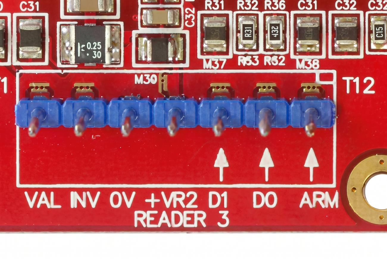
| UniBus 1 (D1) | Door 3 | Inn:X03 | Inn:X11 |
| UniBus 1 (D2) | Door 4 | Inn:X04 | Inn:X12 |
| UniBus 2 (D1) | Door 5 | Inn:X05 | Inn:X13 |
| UniBus 2 (D2) | Door 6 | Inn:X06 | Inn:X14 |
| UniBus 3 (D1) | Door 7 | Inn:X07 | Inn:X15 |
| UniBus 3 (D2) | Door 8 | Inn:X08 | Inn:X16 |
Physical Specifications
- PCB Dimensions: Length 200mm (7.9”) × Width 94mm (3.7”) × Depth 45mm (1.8”).
- Operating Environment: 0°C to 70°C (32°F to 158°F), 15% to 90% Relative Humidity (non-condensing).
- Firmware Compatibility: ISC/IAC Firmware V3.0 or later. Integriti Software V3.0 or later (latest versions recommended).
Configuration / Programming
Status and Fault LEDs
| LED | Name | Indication |
|---|---|---|
| L1 | RX | Valid LAN packet received. Also used for LAN/System fault indication (see fault table below). |
| L2 | TX | LAN packet transmitted. Also used for LAN/System fault indication (see fault table below). |
| L3 | FAULT | ON = LAN fault (see L1/L2 table). FLASHING + L1 FLASHING = Hardware fault (return for repair). FLASHING + L2 FLASHING = Firmware fault (return for repair). |
| L4 | SYS | ON = Module starting up. FLASHING = Module powered and firmware running correctly. |
| L5/L6 | D0/D1 | Reader Data Receive indication for both on-board Reader Inputs. |
| L10/L11 | RX/TX | Reader RS485 port (T1) data receive and transmit indication. |
| L12/L13 | eFuse | Indicates over-current fault on +VR1 or +VR2. |
| L14 | UniBus | FLASHING = Idle (no UniBus boards connected). OFF = OK (UniBus boards communicating). ON = Fault (e.g. address conflict). |
| L16/L17 | Lock | Lock 1 / Lock 2 Relay On indication. |
LAN Fault Code Table (L1/L2)
| L1 | L2 | Explanation / Remedy |
|---|---|---|
| ON | ON | Module is un-addressed (not communicating with Controller). |
| ON | OFF | Too many modules on the network. Check limits and licensing. |
| OFF | ON | Module type unknown. Controller firmware upgrade required. |
| Flash | ON | Duplicate Module address. Number already in use by module of same type. |
| Flash | Flash | Module number selected is too high. Select a lower number or check limits and licensing. |
| ON | Flash | Module disabled (OFF/Flash in earlier firmware versions). |
- Firmware Update Memory Erase: If memory needs to be erased after an update, LEDs L1/L2/L3 will be OFF and L5/L6 will be ON (may take up to 1 minute).
Board Layout
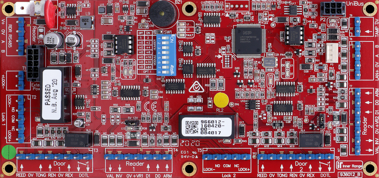
Terminal Pinouts
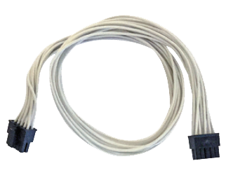
Critical: 10-Pin Power Requirement
This module does not have screw terminals for main power input. It requires a specialized 10-pin power cable connected to the on-board power header:
- P/N 996792: For connection to an Inner Range Smart PSU.
- P/N 996794: For connection to a 3rd Party PSU (Standard DC Input).
LAN Input (T2)
| Terminal | Label | Function | Connection Notes |
|---|---|---|---|
| T2.1 | POS | LAN Power (+) | 11V-14V DC Input. |
| T2.2 | 0V | LAN Power (-) | Reference Ground. |
| T2.3 | A | RS485 LAN A | Data A. |
| T2.4 | B | RS485 LAN B | Data B. |
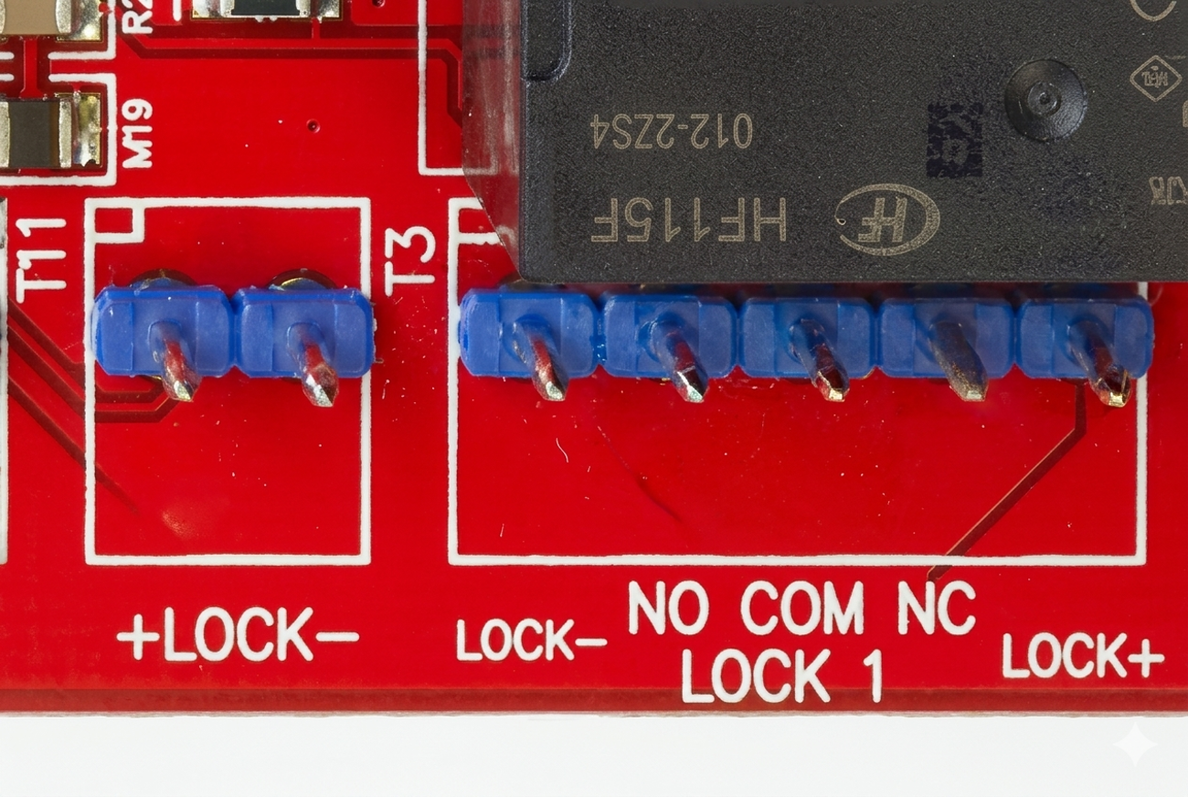
Door 1 Control (T3)
| Terminal | Label | Function | Connection Notes |
|---|---|---|---|
| T3.1 | LOCK1 | Lock 1 Output | Connect to Lock Pos (+). Fit Diode. |
| T3.2 | DOTL1 | Door Open Alert | Connect to Buzzer/LED (+). |
| T3.3 | REED1 | Door Contact In | Connect to Reed Switch. Requires 2k2/2k2 EOL. |
| T3.4 | TONGUE1 | Tongue Sense | Optional tongue sense input. Requires 2k2/2k2 EOL. |
| T3.5 | REX1 | Request to Exit | Connect to Exit Button. Requires EOL. |
| T3.6 | REN1 | Request to Enter | Connect to Entry Button. Requires EOL. |
| T3.7 | 0V | Common (-) | Common Ground for Door 1. |
Reader 1 Power & Data (T4)
| Terminal | Label | Function | Connection Notes |
|---|---|---|---|
| T4.1 | +V | Reader Power (+) | 12V DC Supply (250mA per output limit). Voltage selectable via LK2: 5V or 13.75V. |
| T4.2 | 0V | Reader Power (-) | Reference Ground. |
| T4.3 | VAL1 | Valid Output | Open Collector (100mA). Connect to Reader LED/Beeper. |
| T4.4 | INV1 | Invalid Output | Open Collector (100mA). Connect to Reader LED/Beeper. |
Wiegand Reader 1 (T5)
| Terminal | Label | Function | Connection Notes |
|---|---|---|---|
| T5.1 | D0 | Data 0 | Reader Data 0. |
| T5.2 | D1 | Data 1 | Reader Data 1. |
| T5.3 | LED | LED Control | Reader LED control. |
| T5.4 | BZ | Buzzer Control | Reader Buzzer control. |
| T5.5 | 0V | Common (-) | Reader Ground. |
Door 2 & Reader 2 (T6 - T8)
| Block | Type | Function | Notes |
|---|---|---|---|
| T6 | Door 2 | LCK/DOTL/REED/TONG/REX/REN | Duplicate of Door 1 logic (includes Tongue Sense). |
| T7 | Reader 2 | +V/0V/VAL2/INV2 | Duplicate of Reader 1 Power & VAL/INV. Voltage via LK3. |
| T8 | Wiegand 2 | D0/D1/LED/BZ/0V | Duplicate of Wiegand 1. |
Reader Voltage Selection
- LK2 (Reader 1) and LK3 (Reader 2) select between 5V and 12V (13.75V) for reader power on +VR1/+VR2.
- Recommendation: Use 5V for readers with wide voltage ranges unless 12V is required for maximum read range.
Input Device Supervision
- Door Reed / Tongue Sense: Must be supervised using EOL resistors (standard is 2k2/2k2).
- REX / REN: EOL resistors optional (standard is 2k2/2k2). A Module programming option (“Override EOL”) allows REX/REN to be wired without EOL if permitted (default option).
- ARM Input: Does not require EOL resistors.
- Normally Open Contacts: When programming NO alarm contacts, the “Swap Alarm and Seal” option must be set to [Y]es.
Wiring Diagrams
OSDP Reader Wiring — RDR RS485 Port (T1)
osdp-reader-wiring-ilam.excalidraw
View online: excalidraw.com
Standard Lock Relay Wiring (Common)
Standard Wiegand Reader Wiring (Common)
Door 1 Wiring (ILAM)
graph LR
    subgraph "ILAM Module (T3 & T4)"
        ILAM_LCK[LOCK1]
        ILAM_DOTL[DOTL1]
        ILAM_REED[REED1]
        ILAM_RPOS["+V (Reader Power)"]
        ILAM_GND[0V]
    end

    subgraph "Door Hardware"
        LOCK[Electric Strike]
        DIODE{{1N4004 Diode}}
        BUZZER[DOTL Buzzer]
        SENSOR[Reed Switch]
    end

    %% Wiring
    ILAM_RPOS ==> ILAM_LCK
    ILAM_LCK ==> LOCK
    LOCK --- DIODE
    LOCK ==> ILAM_GND

    ILAM_DOTL ==> BUZZER
    BUZZER ==> ILAM_GND

    ILAM_REED --- SENSOR
    SENSOR --- ILAM_GND