The UniBus 2 Door / 2 Reader Expander (P/N: 996535) adds control and monitoring for 2 additional doors or readers to a compatible UniBus host module, such as the ILAM or IAC.
Technical Details
Capacity: 2 Doors / 2 Wiegand Readers per expander.
Reader Support: Supports Wiegand readers up to 88bits. SIFER/OSDP readers are managed via the host module’s RS485 LAN port, not the expander.
Features: Individual self-resetting overcurrent protection (250mA) on reader outputs, heavy-duty lock relays, and DOTL outputs.
Physical Dimensions: 200mm (L) x 94mm (W) x 45mm (H).
Configuration / Programming
Connectivity: Connects via UniBus patch cable (up to 6 UniBus boards per host module, daisy-chain supported). Maximum combined UniBus cable length is 1620mm.
Firmware: Over-the-wire upgradable via host module. Requires Integriti Controller Firmware V3.0 or later.
DIP Switch (SW1): Switches 1-2 set the starting door numbers (only S1/S2 used for ILAM/IAC):
| Doors | SW1.1 | SW1.2 |
| :--- | :--- | :--- |
| 1 & 2 | OFF | OFF | (Not used with ILAM or IAC) |
| 3 & 4 | ON | OFF |
| 5 & 6 | OFF | ON |
| 7 & 8 | ON | ON |
Max Expanders: 3 UniBus 2-Door Expanders per host. Max 6 total UniBus boards.
Lock/DOTL Relay Auxiliary IDs
Address
Doors
ILAM Lock1
ILAM DOTL1
ILAM Lock2
ILAM DOTL2
IAC Lock1
IAC DOTL1
IAC Lock2
IAC DOTL2
1
3 & 4
X03
X11
X04
X12
X19
X27
X20
X28
2
5 & 6
X05
X13
X06
X14
X21
X29
X22
X30
3
7 & 8
X07
X15
X08
X16
X23
X31
X24
X32
Installation & Wiring
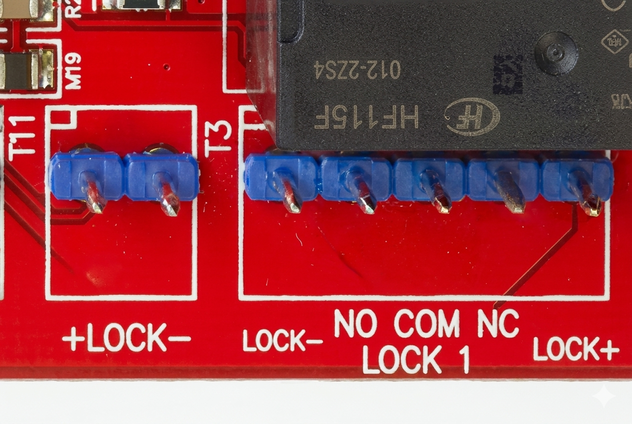
Lock Wiring: T1 provides the dedicated lock power input (Lock+/Lock- from external power-limited, fuse-protected supply). The external power supply must be fuse protected. A 1N4004 protection diode must be fitted as close as possible to the lock. T2 and T5 are the Lock 1 and Lock 2 relay outputs (NO/COM/NC). Heavy-duty Fig. 8 cable (24/0.20 or 14/0.20) recommended for all Power & Lock wiring.
Reader Voltage: Selectable via links LK3/LK4 (5V or 12V).
Zone Wiring: REED and TONGUE inputs require End-of-Line (EOL) resistors. REX and REN inputs can be configured to not require EOL via software (“Override EOL”).
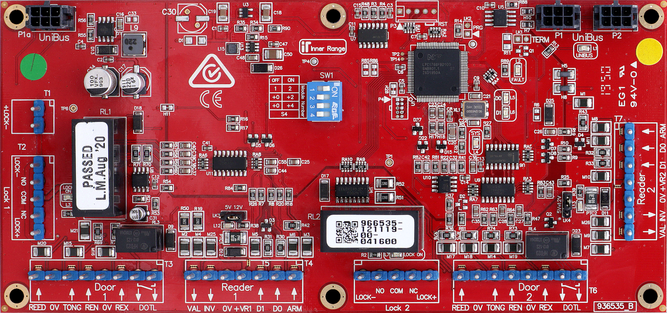
Board Layout
Terminal Pinouts
Lock Power In (T1)
Terminal
Label
Function
Connection Notes
T1.1
+V
Lock Power In (+)
Dedicated Power for Lock 1 & 2.
T1.2
0V
Lock Power In (-)
Common Ground.
Door 1 Relay (T2)
Terminal
Label
Function
Connection Notes
T2.1
COM1
Lock 1 Common
Common for Lock 1 Relay.
T2.2
NO1
Lock 1 N/O
Normally Open contact.
T2.3
NC1
Lock 1 N/C
Normally Closed contact.
Door 1 Inputs/Aux (T3)
Terminal
Label
Function
Connection Notes
T3.1
REED1
Door Contact In
Connect to Reed Switch. Requires EOL.
T3.2
0V
Common (-)
Common Ground for Door 1 inputs.
T3.3
TONG1
Tongue Sense In
Optional Tongue Sense input. Requires EOL.
T3.4
REN1
Request to Enter
Connect to Entry Button. EOL Optional (Override EOL in software).
T3.5
REX1
Request to Exit
Connect to Exit Button. EOL Optional (Override EOL in software).
T3.6
DOTL1
Door Open Alert
DOTL Warning Relay output (+). Connect other contact to 0V.
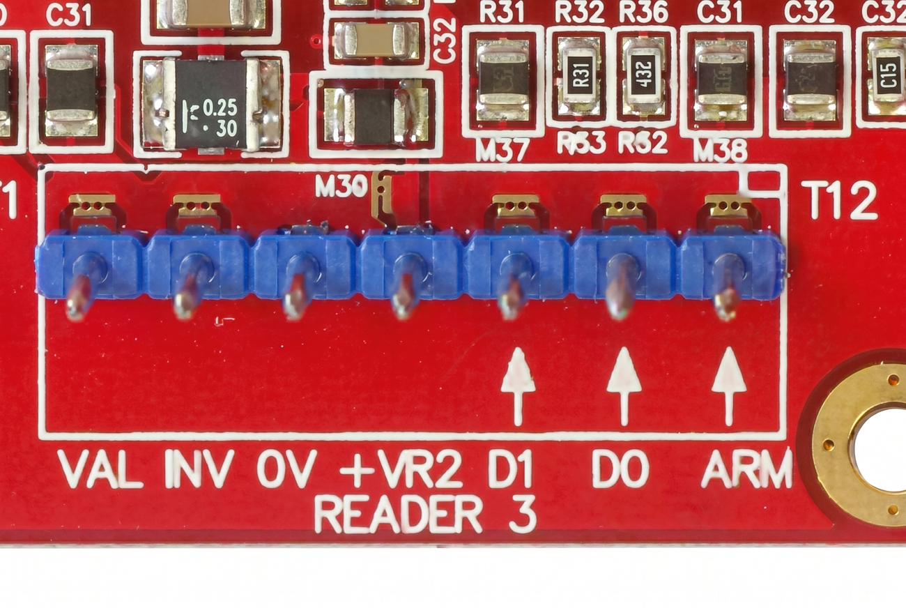
Reader 1 Port (T4) — 7-pin terminal
Terminal
Label
Function
Connection Notes
T4.1
VAL
Reader Valid LED
”Valid” LED output for Reader 1.
T4.2
INV
Reader Invalid LED
”Invalid” LED output for Reader 1.
T4.3
0V
Common (-)
Reader 0 Volt (-ve) connection.
T4.4
+VR
Reader Power (+)
Reader power supply (5V or 12V via LK3/LK4). 250mA self-resetting overcurrent.
T4.5
D1 / CLK
Data 1 / Clock
Reader Data 1 or Clock input.
T4.6
D0 / DATA
Data 0 / Data
Reader Data 0 input.
T4.7
ARM
Arm Button
Optional Area ON control button. EOL NOT required.
Door 2 Relay (T5)
Terminal
Label
Function
Connection Notes
T5.1
COM2
Lock 2 Common
Common for Lock 2 Relay.
T5.2
NO2
Lock 2 N/O
Normally Open contact.
T5.3
NC2
Lock 2 N/C
Normally Closed contact.
Door 2 Inputs/Aux (T6)
Terminal
Label
Function
Connection Notes
T6.1
REED2
Door Contact In
Connect to Reed Switch. Requires EOL.
T6.2
0V
Common (-)
Common Ground for Door 2 inputs.
T6.3
TONG2
Tongue Sense In
Optional Tongue Sense input. Requires EOL.
T6.4
REN2
Request to Enter
Connect to Entry Button. EOL Optional.
T6.5
REX2
Request to Exit
Connect to Exit Button. EOL Optional.
T6.6
DOTL2
Door Open Alert
DOTL Warning Relay output (+).
Reader 2 Port (T7) — 7-pin terminal
Terminal
Label
Function
Connection Notes
T7.1
VAL
Reader Valid LED
”Valid” LED output for Reader 2.
T7.2
INV
Reader Invalid LED
”Invalid” LED output for Reader 2.
T7.3
0V
Common (-)
Reader 0 Volt (-ve) connection.
T7.4
+VR
Reader Power (+)
Reader power supply (5V or 12V). 250mA self-resetting overcurrent.
T7.5
D1 / CLK
Data 1 / Clock
Reader Data 1 or Clock input.
T7.6
D0 / DATA
Data 0 / Data
Reader Data 0 input.
T7.7
ARM
Arm Button
Optional Area ON control button. EOL NOT required.
Installation Environment: 0° to 70°C. 15-90% relative humidity (non-condensing).
EOL Resistor Scheme: Standard is 2k2/2k2 (Controller firmware V3.3.4+). 2k2/6k8 also supported. Firmware prior to V3.3.4 requires 6k8/2k2 for LAN Modules & UniBus boards.
Troubleshooting
LED Diagnostics:
L1 (UNIBUS): OFF = OK. Flashing = Getting Address. Solid ON = Address Clash or Too High — choose another address.
L2 (Fault): OFF = OK. Solid ON during normal operation = Fault detected. ON during bootup or firmware download = OK.
L3: Lock 1 relay ON indicator.
L4 (SYS): Flashing = Module is powered and firmware is running OK.
L5 & L6 (D0/D1): Data receive indication for onboard Reader inputs (active on reader data activity).
L7: Lock 2 relay ON indicator.
L12 (+VR1 Fault): ON = Reader 1 overcurrent fault indication.
L13 (+VR2 Fault): ON = Reader 2 overcurrent fault indication.
Reader Voltage Selection
Reader supply voltage is selected via links LK3 (Reader 1) and LK4 (Reader 2):
Reader Type
LK3/LK4
Omron Magnetic Swipe, HID ProxPoint/MiniProx/ThinLine/iClass R10/R15/R30/R40, HID Swipe/Insertion/Turnstile, Indala SlimLine/WallSwitch/PinProx/ValueProx
Note: Readers with wide supply voltage ranges (e.g. 4V–14V, 5V–16V) are recommended to be powered with 5V unless 12V is required for longer read range.