Integriti Access Controller (IAC)
Overview
The Integriti Access Controller (IAC) is a high-performance IP-connected controller optimized for access control applications. It provides local intelligence for up to 8 doors in-cabinet and supports massive site-wide expansion via RS485 LAN Sub-LAN.
Technical Details
Capacity and Integration
- Users: 100,000 standard (expandable to 1,000,000 with User Expansion Kit).
- Events: 100,000 on-board events whilst offline.
- Doors: 2 on-board (Lock Relays), expandable to 8 via UniBus. Up to 250 doors total via RS485 LAN Sub-LAN.
- Readers:
- 4 Wiegand ports on-board (expandable to 10 via UniBus).
- 1 Dedicated RS485 LAN Reader port (supports up to 16 SIFER/OSDP readers).
- Connectivity: 10/100 Ethernet, USB Master/Slave, RS485 LAN Sub-LAN.
Electrical Specifications
- Power Supply Input: 11V to 14V DC (requires external 3A, 8A, or 10A SMART PSU).
- Current Consumption:
- Standby: 150mA.
- On-board Lock Relays Active: 220mA.
- DOTL Relay Active: +15mA per relay.
- Note: Excludes readers, locks, and UniBus modules.
- Max Ancillary Current (LAN+, RDR RS485+, DET+, UniBus, USB-H combined):
- 3A PSU: 2.2A.
- 8A PSU: 6A.
- Memory: 4 GB Micro SD for controller database and review event log.
- Reader Head Supply: Selectable 5V or 13.8V DC. 300mA max per reader, 1A total.
- Lock Relays: 5 Amps @ 30V DC.
- DOTL Relays: 1 Amp @ 30V DC.
UniBus Expansion Limits
The IAC supports a maximum of 6 UniBus boards total. Specific device limits include:
| UniBus Board Type | Max Supported |
|---|---|
| 2 Door / 2 Reader Expander | 3 |
| 8 Relay Expander | 2 |
| 16 Floor Lift Interface | 6 |
| RS232/RS485 LAN UART | 4 |
⚠️ Important: UniBus 8 Zone Expanders are NOT supported on the IAC.
Board Layout
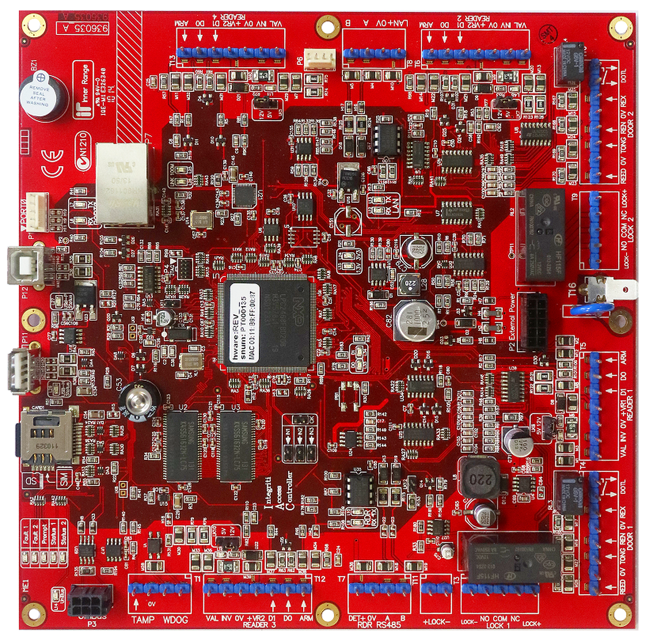
Terminal Pinouts
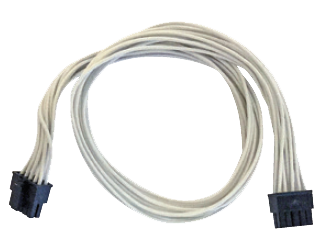
Critical: 10-Pin Power Requirement
This module does not have screw terminals for main power input. It requires a specialized 10-pin power cable connected to the on-board power header:
- P/N 996792: For connection to an Inner Range Smart PSU.
- P/N 996794: For connection to a 3rd Party PSU (Standard DC Input).
RS485 Sub-LAN (T2 & T3)
| Terminal | Label | Function | Connection Notes |
|---|---|---|---|
| POS | +V | LAN Power (+) | 13.8V DC supply for LAN Modules. |
| 0V | 0V | LAN Power (-) | Reference Ground. |
| A | A | RS485 LAN A | Data A. |
| B | B | RS485 LAN B | Data B. |
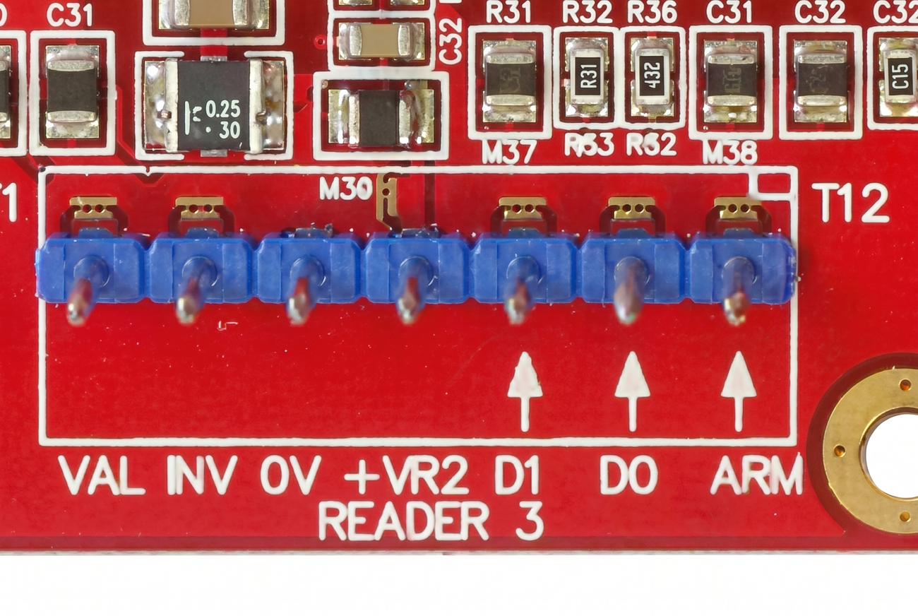
Reader Ports (T5 - T7)
| Block | Type | Terminals | Function |
|---|---|---|---|
| T5 | Wiegand 1/2 | D0, D1, LED, BZ, 0V, +V | Connection for 2 Wiegand Readers. |
| T6 | Wiegand 3/4 | D0, D1, LED, BZ, 0V, +V | Connection for 2 Wiegand Readers. |
| T7 | RS485 LAN Reader | A, B, 0V, +V | Multi-drop port for SIFER/OSDP. |
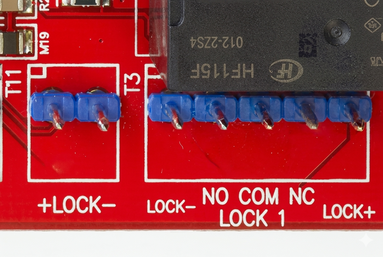
Door 1 & 2 Control (T11)
| Terminal | Label | Function | Connection Notes |
|---|---|---|---|
| T11.1 | +V1 | Lock Power In (+) | Dedicated Power for Lock 1. |
| T11.2 | LCK1 | Lock 1 Output | Connect to Lock Pos (+). Fit Diode. |
| T11.3 | 0V | Common (-) | Lock Negative (-) connection. |
| T11.4 | +V2 | Lock Power In (+) | Dedicated Power for Lock 2. |
| T11.5 | LCK2 | Lock 2 Output | Connect to Lock Pos (+). Fit Diode. |
Wiring Diagrams
Standard Lock Relay Wiring (Common)
Standard Wiegand Reader Wiring (Common)
Standard Door 1 Wiring (IAC)
graph LR
    subgraph "IAC Module (T11 & T5)"
        IAC_V1["+V1 (Lock Power In)"]
        IAC_L1["LCK1 (Lock Out)"]
        IAC_D0[D0]
        IAC_D1[D1]
        IAC_GND[0V]
    end

    subgraph "Lock & Reader"
        LOCK[Electric Strike]
        DIODE{{1N4004 Diode}}
        READER[Wiegand Reader]
    end

    %% Wiring
    IAC_V1 ==> IAC_L1
    IAC_L1 ==> LOCK
    LOCK --- DIODE
    LOCK ==> IAC_GND

    READER --- IAC_D0
    READER --- IAC_D1
    READER --- IAC_GND
Ordering Options
The IAC is available as a PCB or in kitted enclosures:
- PCB Only: 996035PCB&K.
- 2 Door Kit: Medium enclosure, 3A Smart PSU (IK-996035M2PS).
- 8 Door Kit: WideBody enclosure, 8A Smart PSU, 3x UniBus 2 Door Expanders (IK-996035WB8PS).