The UniBus 2 Port UART provides two high-speed, software-configurable serial ports (RS232 or RS485 LAN) for connecting peripheral devices like computers, modems, or intercom systems.
Technical Details
Ports: 2 software-configurable ports.
Port 1 (Modem): Supports all Comms Task formats requiring UART Serial Port communications, including “E Modem”.
Port 2 (Comm): Supports formats using TXD/RXD and CTS/RTS (e.g. Integriti, Monitor, GSM, Automation, EMS, Securitel, Intercom, BMS). Does not support CD, DSR, DTR, or RI (use Port 1 for these).
Pre-assembled Cables: Available for DB9 (993009), DB25 (993026, 993027), Printer, Modem, and Securitel (993035) connections.
Host Compatibility:
Integriti ISC Controller (Connect up to 4).
Integriti IAC Controller (Connect up to 4).
Intercom Integration: Supported for Aiphone GT Series and IIS (Kenwei).
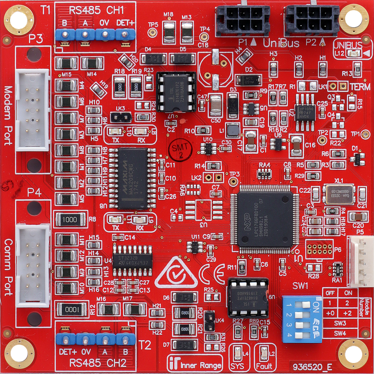
Board Layout
Terminal Pinouts
Port 1 - Modem (T1)
Terminal
Label
Function
Connection Notes
T1.1
+V
Port Power (+)
12V DC Supply for peripherals.
T1.2
TX / A
Transmit / Data A
RS232 TX or RS485 LAN A.
T1.3
RX / B
Receive / Data B
RS232 RX or RS485 LAN B.
T1.4
RTS
Request Send
RS232 Handshaking.
T1.5
CTS
Clear Send
RS232 Handshaking.
T1.6
DTR / POS
Ready / LAN Pos
Modem Control or LAN Power.
T1.7
DSR / 0V
Ready / LAN Neg
Modem Control or LAN Ground.
T1.8
CD
Carrier Detect
Modem Control.
T1.9
RI
Ring Indicator
Modem Control.
T1.10
0V
Ground
Common Reference.
Port 2 - Comm (T2)
Terminal
Label
Function
Connection Notes
T2.1
+V
Port Power (+)
12V DC Supply.
T2.2
TX / A
Transmit / Data A
RS232 TX or RS485 LAN A.
T2.3
RX / B
Receive / Data B
RS232 RX or RS485 LAN B.
T2.4
RTS
Request Send
RS232 Handshaking.
T2.5
CTS
Clear Send
RS232 Handshaking.
T2.6
0V
Ground
Common Reference.
Note
Limits
Restricted Port
Port 2 does NOT support full Modem.
Configuration / Programming
Addressing: Set via DIP switches (Modules 1-4).
Mode Selection: DIP switches used to select RS232 or RS485 LAN per port.
Firmware: Over-the-wire upgradable.
Indicators: Features 2 LED system status/fault indicators and LED indication of CH1 & CH2 RX & TX activity.
Specifications
Power Supply Input: 11V to 14V DC via host module.
Current Consumption: 40mA PLUS 5mA per active port.
Physical Dimensions: 105mm (L) × 94mm (W) — 94mm with snap-off strip removed. Depth: 28mm with UniBus cable connected.
Connection to Host: Via 270mm UniBus patch lead (supplied).
Installation Environment: 0°C to 70°C, 15% to 90% Relative humidity (non-condensing).
Max UniBus Boards: Up to 4 UniBus 2 Port UART boards per host. Max 6 total UniBus boards. Combined UniBus cable length ≤ 1620mm.
Addressing and Mode Selection
UART Address
DIP 1
DIP 2
1
OFF
OFF
2
ON
OFF
3
OFF
ON
4
ON
ON
DIP Switch
OFF
ON
S3 (CH1 - Port 1)
RS232 (Modem)
RS485
S4 (CH2 - Port 2)
RS232 (Comm)
RS485
Pre-assembled Cables
P/N
Description
993009
Computer interface cable (DB9)
993025
Computer interface cable (DB25)
993026
Serial Printer interface cable (DB25)
993027
Modem interface cable (DB25)
993035
Securitel interface cable (Flying leads)
995009
Internal PC Interface cable kit (internal DB9 knockout)
Troubleshooting
LED Diagnostics
L12 (UNIBUS): OFF = OK. Flashing = Getting Address. ON = Address Clash or Too High.
L2 (Fault): OFF = OK. ON during normal operation = Fault detected. ON during bootup or firmware download = OK.
L4 (SYS): Flashing = OK (module powered and firmware running).
L8–L11: UART Port Transmit/Receive activity indicators.