UniBus 8 Zone Expander
Overview
The UniBus 8 Zone Expander Kit connects to an ISC or 8-32 Zone LAN Expander Module via the UniBus Port to provide an additional 8 Zone Inputs. It also includes extra detector power supply connections (DET+) to simplify device wiring.
Technical Details
Electrical Specifications
- Power Supply Input: 13.75V DC via the UniBus connection.
- Current Consumption: 50mA (Base consumption; does not include detectors, lamps, or other peripherals).
- DET+ Output: +13.75V DC ±2% (Protected via host module detector fuse).
- Overcurrent Protection: Protected via self-resetting electronic fuses on the host module’s Smart Power Supply.
Physical Specifications
- PCB Dimensions: 94mm (L) × 94mm (W) × 15mm (H) (28mm with UniBus cable connected).
- Operating Temperature: 0°C to 70°C (32°F to 158°F).
- Humidity: 15% to 90% Relative humidity (non-condensing).
Installation Constraints
- Host Compatibility:
- Integriti ISC.
- Integriti 8-32 Zone LAN Expander.
- UniBus Limits: A maximum of 6 UniBus boards can be connected to a single host module.
- Cable Length: Total combined length of all UniBus cables must not exceed 1620mm.
- Enclosure: Must be installed in the same enclosure as the host module.
Board Layout
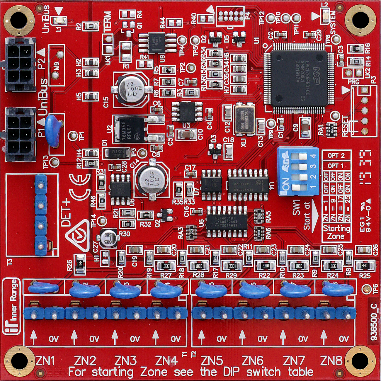
Terminal Pinouts
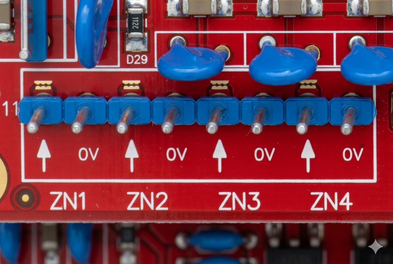
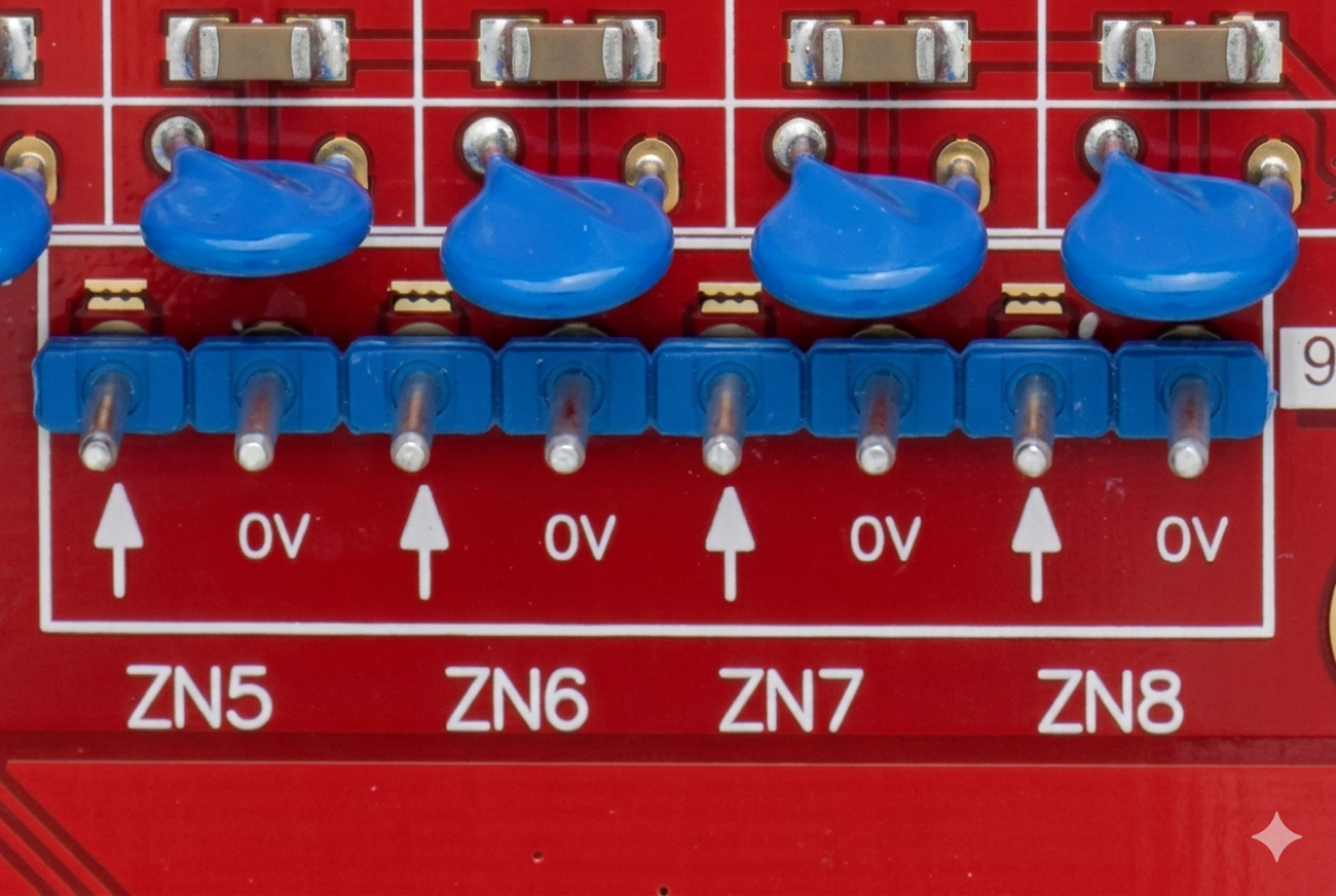
Zone Inputs (T1 & T2)
| Block | Label | Function | Connection Notes |
|---|---|---|---|
| T1 | Z(n) - Z(n+3) | Inputs 1-4 | 4 Configurable Inputs + Common 0V. |
| T2 | Z(n+4) - Z(n+7) | Inputs 5-8 | 4 Configurable Inputs + Common 0V. |
| Note | EOL | End-of-Line | Supports standard Integriti/Inception EOL. |
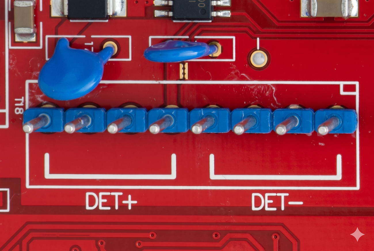
Detector Power (T3)
| Terminal | Label | Function | Connection Notes |
|---|---|---|---|
| T3.1 | DET+ | Detector Pos (+) | 13.75V DC Out (Fused). |
| T3.2 | 0V | Detector Neg (-) | Reference Ground. |
Wiring Diagrams
Standard Detector Power Wiring (Common)
Standard Zone Wiring (Common)
Addressing and Assignment
The zone numbers assigned to the expander are determined by DIP switches S1 and S2 on SW1:
| Zones | DIP 1 | DIP 2 |
|---|---|---|
| 1 to 8 | OFF | OFF |
| 9 to 16 | ON | OFF |
| 17 to 24 | OFF | ON |
| 25 to 32 | ON | ON |
Note: If connecting to an Integriti Security Controller, the UniBus Zone Expander is typically assigned Zones 17 to 24 or 25 to 32.
Configuration / Programming
Input Wiring
- EOL Support: Supports the full range of Integriti/Inception End-Of-Line resistor configurations.
- Normally Open Contacts: When programming zone inputs for NO alarm contacts, the “Swap Alarm and Seal” option must be enabled for that zone.
- Detector Power (T3): Provides +13.75V DC output. Use the Zone I/P “0V” terminal for the detector 0V (DET-) connection.
Troubleshooting
LED Diagnostics
- L1 (UniBus Status):
- OFF: OK.
- Flashing: Getting Address.
- ON: Address clash or address too high.
- L2 (System Status): Slow Flash indicates OK.
Related UniBus Modules
- UniBus 8 Relay Auxiliary Expander
- UniBus 2 Door Expander
- UniBus 16 Floor Lift Interface
- UniBus Analogue Input Expander
- UniBus 2 Port UART