UniBus 16 Floor Lift Interface
Overview
The UniBus 16 Floor Lift Interface module provides low-level integration between Inner Range systems and lift controllers. It manages 16 floors per device and includes button feedback sensing to facilitate secure floor access control.
Technical Details
Capacity and Integration
- Capacity: 16 floors per device.
- Expansion: Connect up to 6 modules per host controller for a single lift car, servicing up to 96 floors.
- Host Compatibility: Integriti ISC, Integriti IAC, 8 Zone LAN Expander, and ILAM.
- Isolation: Provides required electrical isolation between the security and lift systems.
- Override: Includes an override input for free access mode.
Electrical Specifications
- Power Supply Input: 11V to 14V DC via host module.
- Current Consumption:
- Base: 55mA.
- Per Active Relay: +16mA.
- Total (All Relays ON): ~310mA.
- Button Input Voltage: 16 – 110V DC full wave rectified non-regulated.
- Contact Rating (Relays):
- 500mA @ 16 – 48V DC/AC RMS.
- 200mA @ 60 – 110V DC/AC RMS (30W / 62.5VA).
- Replacement Relay: Panasonic TQ2-12V (socketed).
Physical Specifications
- PCB Dimensions: 200mm (L) × 94mm (W). Depth: 28mm with UniBus cable connected.
- Operating Temperature: 0°C to 70°C (32°F to 158°F).
- Humidity: 15% to 90% Relative humidity (non-condensing).
- Firmware Requirements: Integriti Software/Controller Firmware V2.5.1 or later; Inception Firmware V1.0.0 or later.
Board Layout
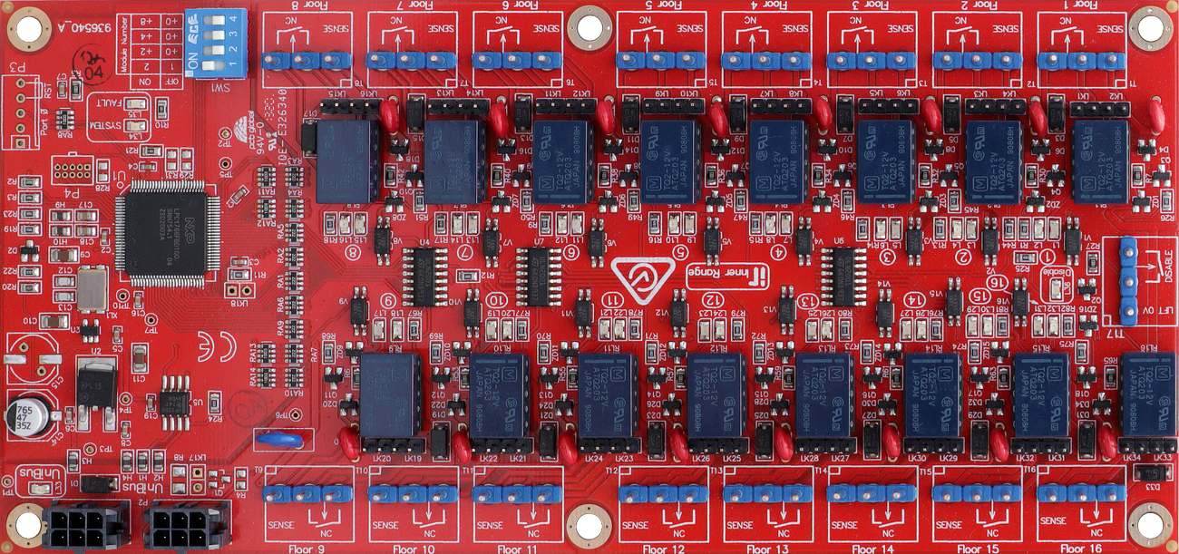
Terminal Pinouts
Floor Wiring Terminals (T1 – T16)
Each of T1 through T16 provides connections for one floor (16 floors total):
| Terminal Block | Label | Function | Connection Notes |
|---|---|---|---|
| T(n).1 | SENSE | Floor Button Sense | Connect to Floor button feed or EMS button sense input. See link settings. |
| T(n).2 | NC | Normally Closed Output | Connect to Lift Control equipment button sense wire. Relay is normally active — de-activates to select floor. |
| T(n).3 | COM | Relay Common | Common for NC relay contact and button circuit. |
System Inputs (T17)
| Terminal | Label | Function | Connection Notes |
|---|---|---|---|
| T17.1 | LIFT 0V | Lift System Ground | MUST be connected to common 0V (power supply -ve) on the Lift system. |
| T17.2 | DISABLE | Override Input | MUST be connected to Normally Closed over-ride switch. Closed = power to floor relays. Open = free access on all floors. |
Connectivity
Physical I/O
- Relay Contacts: 16 x NC outputs for floor access.
- Button Sense Inputs: 16 inputs for user button feedback (supports a wide range of voltages).
- Override Input: 1 input to allow “free access” mode.
- UniBus Ports: 1 Input and 1 Loop-through port for daisy-chaining multiple UniBus boards.
Configuration / Programming
- Addressing (SW1): 4-position DIP switch (S1–S4) sets the starting floor for the interface board: | Floors | DIP 1 | DIP 2 | DIP 3 | DIP 4 | | :--- | :--- | :--- | :--- | :--- | | 1 – 16 | OFF | OFF | OFF | OFF | | 17 – 32 | ON | OFF | OFF | OFF | | 33 – 48 | OFF | ON | OFF | OFF | | 49 – 64 | ON | ON | OFF | OFF | | 65 – 80 | OFF | OFF | ON | OFF | | 81 – 96 | ON | OFF | ON | OFF |
- Link Settings: Odd-numbered links (LK1–LK15, LK19–LK33) fitted when button lamp feedback sourced via Lift Controller. Even-numbered links (LK2–LK16, LK20–LK34) fitted when button is wired directly to Sense (remove if separate circuits).
- Connectivity: Connects via UniBus patch cable (270mm supplied). Up to 6 Lift Interface boards per host. Max 6 total UniBus boards. Combined UniBus cable ≤ 1620mm.
- Firmware: Over-the-wire upgradable via the host module.
Troubleshooting
LED Diagnostics
- L1–L31 (Odd): ON = +ve feed voltage present on NC terminals. Also follows Floor button lamp when lamp feedback sourced via Lift Controller.
- L2–L32 (Even): ON = Floor Access Relay active. Note: Relays are normally active and de-activate to select the floor. All OFF when in Disabled mode.
- L33 (UNIBUS): OFF = OK. Flashing = Getting Address. ON = Address Clash or Too High.
- L34 (SYS): Flashing = OK (module powered and firmware running).
- L35 (FAULT): OFF = OK. ON during normal operation = Fault detected. ON during bootup or firmware download = OK.
- L34/L35 Alt Flash: Firmware Update in progress (fast alternate flashing).
- L36 (DISABLE): ON = Security disabled, all floors in free access (DISABLE input is open circuit).
Related UniBus Modules
- UniBus 2 Door Expander
- UniBus 8 Zone Expander
- UniBus 8 Relay Auxiliary Expander
- UniBus Analogue Input Expander
- UniBus 2 Port UART