UniBus Analogue Input Expander
Overview
The UniBus 4 Way Analogue Input Expander allows for the monitoring and reporting of analogue values (voltage, current, or serial temperature) within an Integriti system.
Technical Details
- Inputs: 4 Universal Analogue Zone Inputs.
- Operating Modes:
- Serial Mode: For use with the Inner Range Serial Temperature Sensor (Part 994089).
- Voltage Monitor: 0 to 10V DC.
- Current Loop: 4 to 20mA DC.
- Host Compatibility:
- Integriti ISC (Connect up to 4).
- 8 Zone LAN Expander (Connect up to 6).
- Firmware Requirements: Integriti Controller firmware V17 or later; 8-Zone LAN Expander firmware V1.2 or later.
Physical Specifications
- PCB Dimensions: 105mm (L) × 94mm (W) — 94mm with snap-off strip removed. Height: 15mm (28mm with UniBus cable connected).
- Operating Temperature: 0°C to 70°C (32°F to 158°F).
- Humidity: 15% to 90% Relative humidity (non-condensing).
Board Layout
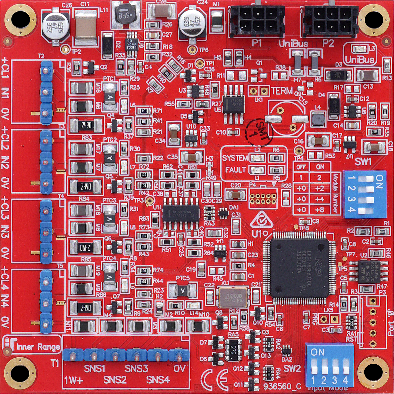
Terminal Pinouts
Serial Temperature Sensors (T1)
| Terminal | Label | Function | Connection Notes |
|---|---|---|---|
| T1.1 | SNS1 | Sensor 1 Data | Serial input from Sensor 1. |
| T1.2 | SNS3 | Sensor 3 Data | Serial input from Sensor 3. |
| T1.3 | 0V | Sensor Neg | Common return for sensors. |
| T1.4 | 1W+ | Sensor Power (+) | +5V DC supply for P/N 994089 sensors. |
| T1.5 | SNS2 | Sensor 2 Data | Serial input from Sensor 2. |
| T1.6 | SNS4 | Sensor 4 Data | Serial input from Sensor 4. |
Analogue Zone Inputs (T2 - T5)
| Block | Label | Function | Connection Notes |
|---|---|---|---|
| T2.1 | +24V | Loop Power | Current Loop supply (20mA). |
| T2.2 | IN1 | Analogue In 1 | 0-10V or 4-20mA Input. |
| T2.3 | 0V | Common (-) | Reference Ground. |
| T3-T5 | (As Above) | Inputs 2 - 4 | Grouped identically to T2. |
Configuration / Programming
- Addressing (SW1): DIP switch SW1 sets the starting zone address. Uses switches 1, 2, and 3: | Zones | DIP 1 | DIP 2 | DIP 3 | Notes | | :--- | :--- | :--- | :--- | :--- | | 1 to 4 | OFF | OFF | OFF | Not valid for ISC | | 5 to 8 | ON | OFF | OFF | Not valid for ISC | | 9 to 12 | OFF | ON | OFF | Not valid for ISC | | 13 to 16 | ON | ON | OFF | Not valid for ISC | | 17 to 20 | OFF | OFF | ON | | | 21 to 24 | ON | OFF | ON | | | 25 to 28 | OFF | ON | ON | | | 29 to 32 | ON | ON | ON | |
- ISC Note: Analogue Expander Zones on a Security Controller must start at Zone 17, 21, 25, or 29.
- 8-32 Zone Expander Note: Zones must start at 9, 13, 17, 21, 25, or 29.
- Input Mode (SW2): DIP switch SW2 selects the mode per input. OFF = Voltage/Serial Mode. ON = Current Mode.
- Wiring Connections:
- T1: Serial Temperature Sensor inputs and +5V supply.
- T2 - T5: Analogue Zone Inputs and +24V Current Loop supply.
- Calibrations: Default calibrations provided in Integriti for testing include “Unibus Alog 0-10 Volts”, “Unibus Alog 4-20mA as mA”, and “Unibus Alog 994089 Temp Sensor”.
- Thresholds: Trigger points, tamper levels, and hysteresis are individually configurable per input.
- Firmware: Over-the-wire upgradable.
Specifications
- Power Supply Input: 11V to 14V DC via host module.
- Current Consumption: 50mA idle, up to 230mA max (with all current loops supplying 20mA).
- Supply Outputs: 24V DC for current loops (individually PTC protected), +5V DC (1W+) for serial sensors.
- Input Range: 0–10V DC (Voltage mode), 4–20mA DC (Current Loop mode), -55°C to +125°C (Serial Temp Sensor).
Serial Temperature Sensor (P/N 995089)
- Range: -55°C to +125°C.
- Resolution: 0.5°C steps.
- Accuracy: ±0.5°C (0–70°C), ±1.0°C (70–85°C), ±2.0°C (85–125°C).
- Supply: +5V DC from UniBus Analogue Expander.
- Max Cable Distance: 25 metres (min. 3-core cable).
Troubleshooting
LED Diagnostics
- L1 (FAULT): OFF = OK. ON during normal operation = Fault detected. ON during bootup/firmware download = OK.
- L2 (STATUS): Slow Flash = OK (module powered and firmware running).
- L3 (UNIBUS STATUS): OFF = OK. Flashing = Getting Address. ON = Address clash or too high.
- L6–L9 (CURRENT LOOP OC): OFF = OK. ON = Overcurrent condition on associated +CL1 to +CL4 current loop supply output.
- L14 (SERIAL SENSOR OC): OFF = OK. ON = Overcurrent condition on Serial Temperature Sensor supply output (1W+).
Related UniBus Modules
- UniBus 8 Zone Expander
- UniBus 8 Relay Auxiliary Expander
- UniBus 2 Door Expander
- UniBus 16 Floor Lift Interface