8 Zone LAN Expander
Overview
The 8 Zone LAN Expander Module (P/N: 996005) connects to Inner Range controllers via RS485 LAN to provide an additional 8 Zone Inputs, 2 Auxiliary Outputs, and 2 Siren drivers. It features a UniBus in-cabinet expansion interface for further local expansion.
Technical Details
- Connectivity: RS485 LAN (up to 99 modules per system). Identifies as “Wired Zone Expander” on Integriti and “8 Input Expander” on Inception.
- Expansion: UniBus interface (P3) supports up to 6 UniBus boards total.
- Up to 3 x UniBus 8 Zone Expander boards.
- Up to 4 x UniBus 8 Relay Auxiliary Expander boards.
- Up to 6 x UniBus 16 Floor Lift Interface boards.
- Inputs: 8 Zone Inputs (Multistate or Analogue). Default EOL is 2k2 / 2k2.
- Outputs: 2 Auxiliary NO/NC Relay Outputs, 2 Siren drivers (Internal & External variable tone).
- Physical Dimensions: 200mm (L) x 94mm (W) x 45mm (H).
Board Layout
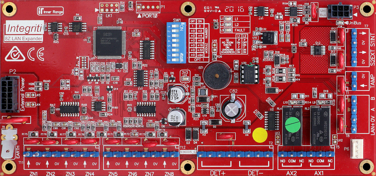
Terminal Pinouts
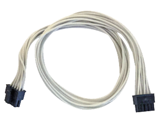
Critical: 10-Pin Power Requirement
This module does not have screw terminals for main power input. It requires a specialized 10-pin power cable connected to the on-board power header:
- P/N 996792: For connection to an Inner Range Smart PSU.
- P/N 996794: For connection to a 3rd Party PSU (Standard DC Input).
LAN Data (T1)
| Terminal | Label | Function | Connection/Wiring Notes |
|---|---|---|---|
| T1.3 | A | RS485 A | Data A. |
| T1.4 | B | RS485 B | Data B. |
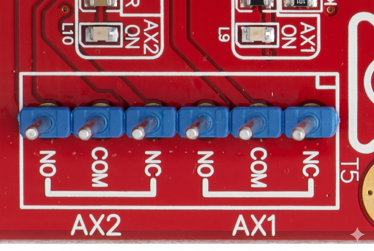
Auxiliary Outputs (T2)
| Terminal | Label | Function | Connection/Wiring Notes |
|---|---|---|---|
| AUX1 | C, NO, NC | Aux Relay 1 | SPDT Relay (30V DC / 2A). |
| AUX2 | C, NO, NC | Aux Relay 2 | SPDT Relay (30V DC / 2A). |
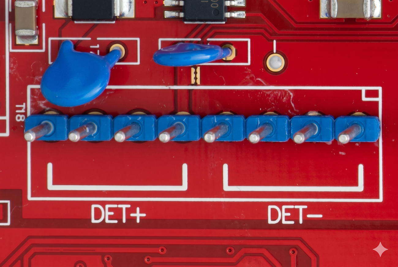
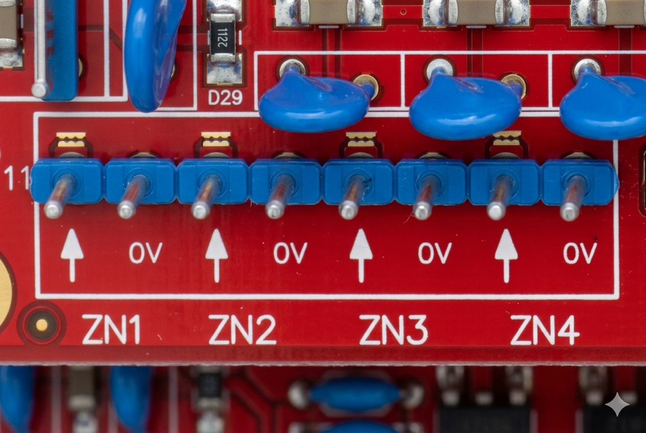
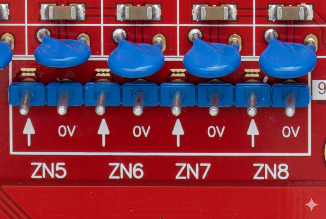
Zone Inputs (T3 & T4)
| Block | Label | Function | Connection/Wiring Notes |
|---|---|---|---|
| T3 | Z1 - Z4 | Inputs 1-4 | 4 Configurable Inputs + Common 0V. |
| T4 | Z5 - Z8 | Inputs 5-8 | 4 Configurable Inputs + Common 0V. |
| Note | EOL | End-of-Line | Standard: 2k2 Series / 2k2 Parallel. |
Siren Drivers (T5)
| Terminal | Label | Function | Connection/Wiring Notes |
|---|---|---|---|
| S1INT | POS, 0V | Internal Siren | 12V DC / 2.3A (Variable Tone). |
| S2EXT | POS, 0V | External Siren | 12V DC / 2.3A (Variable Tone). |
Wiring Diagrams
Standard Detector Power Wiring (Common)
Standard Auxiliary Relay Wiring (Common)
Standard Zone Wiring (Common)
Configuration / Programming
- Addressing: Module number is set using DIP switches 1 to 7 as binary + 1. DIP switch 8 is not used and must be OFF.
- Aux Mapping: Relays can be used for general purpose outputs when mapped to Aux 1~16 on the controller.
- Firmware: Over-the-wire upgradable. Revision D PCBs must run V3.2.0 or later.
Installation & Wiring
- Siren Cabling: Two siren outputs (S1INT, S2EXT). A maximum of two 8 Ohm Siren speakers may be connected to each siren output, wired in parallel.
- Tamper: Features terminals for a cabinet tamper switch (normally closed).
- Power: When UniBus boards or Siren Speakers are connected, the module must be powered by an external 10-way bus cable to an Integriti Smart Power Supply.
Specifications
- Power Supply Input: 11V to 14V DC.
- Current Consumption: 60mA standby, 100mA with both Aux relays on.
- Detector Power: +12V output. Max total ancillary current (DET+ & UniBus & LAN+) is 1.2A.
- Relay Rating: 2 Amps at up to 30V DC, 1 Amp at up to 30V AC RMS.
- Siren Speaker Output: 2.3A, minimum load impedance 4 Ohms.
Troubleshooting
- L3 (FAULT) LED Indicators:
- L1 ON, L2 OFF: NO ROOM (Too many modules on network).
- L1 Flash, L2 ON: EXISTS (Duplicate module address).
- L1 Flash, L2 Flash: DIMENSION (Module number too big).
- L1 OFF, L2 ON: UNKNOWN (Firmware upgrade required).
- L1 ON, L2 ON: NO ADDRESS (Not communicating with controller).
Related UniBus Modules
- UniBus 8 Zone Expander
- UniBus 8 Relay Auxiliary Expander
- UniBus 16 Floor Lift Interface
- UniBus Analogue Input Expander