UniBus 8 Relay Auxiliary Expander
Overview
The UniBus 8 Relay Expander provides eight independent, high-current NO/NC relay outputs for general-purpose automation, access control, and warning device control. It connects directly to a host controller or LAN module via the UniBus port.
Technical Details
Electrical Specifications
- Power Supply Input: 13.75V DC via UniBus connection.
- Operating Voltage Range: 11V to 14V DC.
- Current Consumption:
- Base: 45mA.
- Per Active Relay: +25mA.
- Total (All Relays ON): ~245mA.
- Relay Contact Ratings:
- Max DC: 1.0 Amp @ 24V DC.
- Max AC: 0.5 Amp @ 30V AC (RMS).
Physical Specifications
- PCB Dimensions: 105mm (L) × 94mm (W) — 94mm with snap-off strip removed. Depth: 28mm with UniBus cable connected.
- Operating Temperature: 0°C to 70°C (32°F to 158°F).
- Humidity: 15% to 90% Relative humidity (non-condensing).
Installation Constraints
- Host Compatibility:
- Integriti ISC / IAC.
- Integriti 8 Zone LAN Expander.
- Integriti ILAM.
- Inception Controller.
- UniBus Limits: A maximum of 6 UniBus boards can be connected to a single host module.
- Cable Length: Total combined length of all UniBus cables must not exceed 1620mm.
- Mounting: Mounted in the same enclosure as the host. Supports stacking above Size B boards using 35mm standoffs.
Board Layout
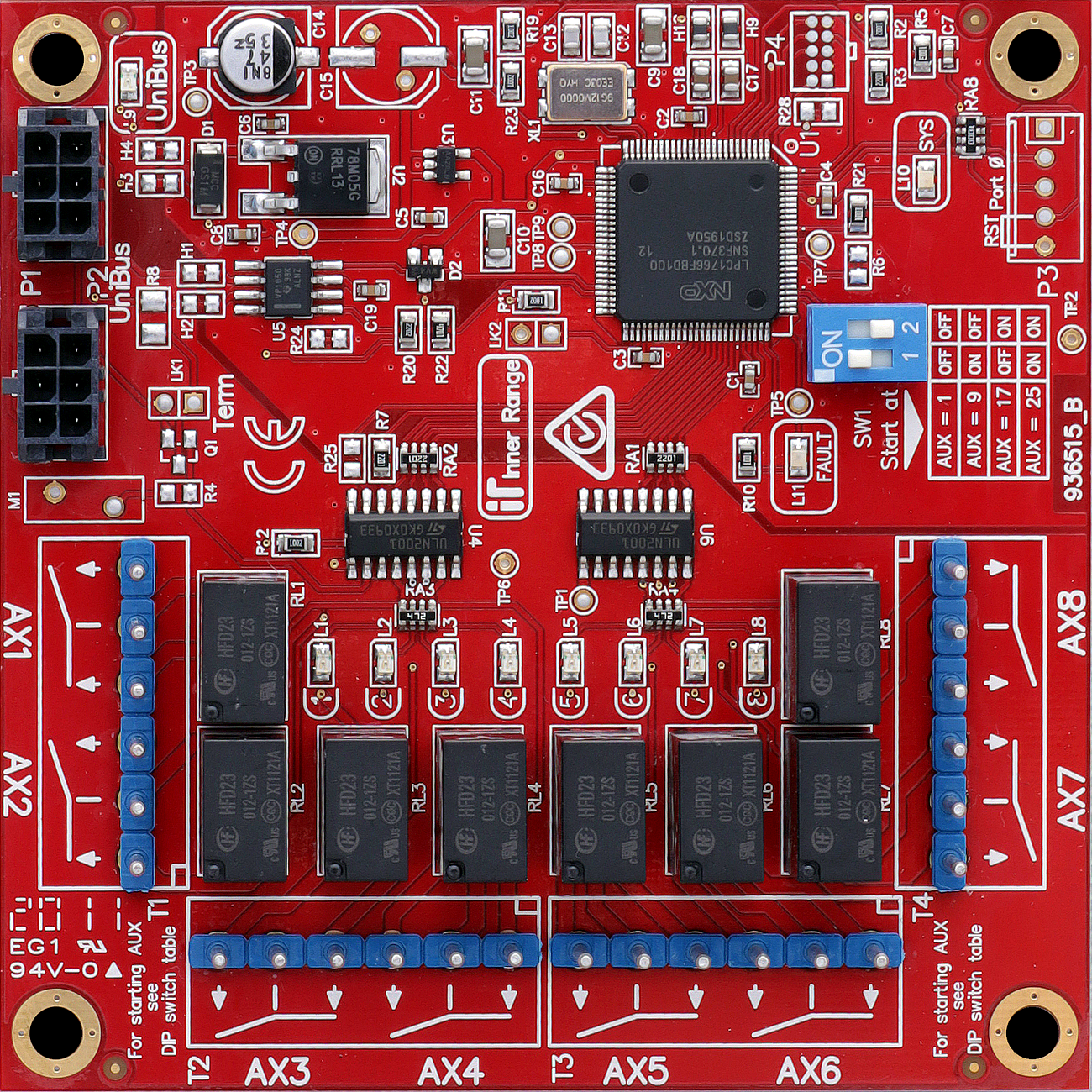
Terminal Pinouts
Relay Outputs (T1 - T4)
| Block | Label | Function | Connection Notes |
|---|---|---|---|
| T1 | C, NO, NC (x2) | Relays 1 & 2 | SPDT (24V DC / 1A). |
| T2 | C, NO, NC (x2) | Relays 3 & 4 | SPDT (24V DC / 1A). |
| T3 | C, NO, NC (x2) | Relays 5 & 6 | SPDT (24V DC / 1A). |
| T4 | C, NO, NC (x2) | Relays 7 & 8 | SPDT (24V DC / 1A). |
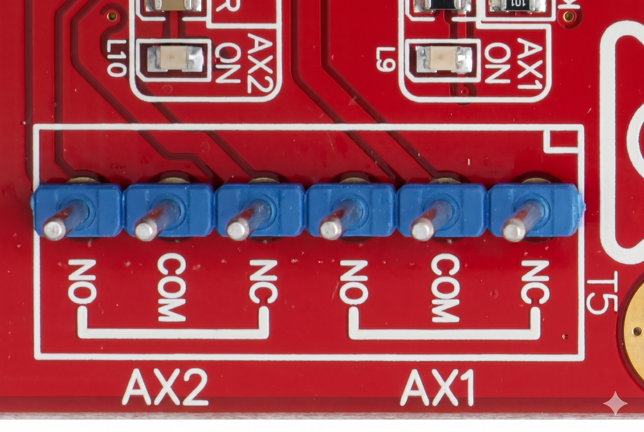
Wiring Diagrams
Standard Auxiliary Relay Wiring (Common)
Addressing and Assignment
The auxiliary numbers assigned to the expander are determined by DIP switches S1 and S2 on SW1:
| Auxiliaries | DIP 1 | DIP 2 |
|---|---|---|
| 1 to 8 | OFF | OFF |
| 9 to 16 | ON | OFF |
| 17 to 24 | OFF | ON |
| 25 to 32 | ON | ON |
Note: When used with an ILAM, Auxiliaries 1-8 are reserved for on-board lock control, so the first expander is typically set to 9-16.
Troubleshooting
LED Diagnostics
- L1 to L8: Indicate individual relay status (ON when relay is active).
- L9 (UniBus Status):
- OFF: OK.
- Flashing: Getting Address.
- ON: Address clash or address too high.
- L10 (SYS): Flashing indicates normal system operation.
- L11 (Fault): OFF = OK. ON during normal operation = Fault has been detected. ON during bootup or firmware download = OK.
Related UniBus Modules
- UniBus 8 Zone Expander
- UniBus 2 Door Expander
- UniBus 16 Floor Lift Interface
- UniBus Analogue Input Expander
- UniBus 2 Port UART