Integriti Security Controller (ISC)
Overview
The Integriti Security Controller (ISC) is an IP-based master controller for the Integriti modular hardware system. It serves as the central processing unit for security, access control, and automation logic, supporting extensive expansion via UniBus and RS485 LAN Sub-LAN.
Technical Details
Capacity and Integration
- Users: 100,000 standard (expandable to 1,000,000 with Level 5 User Expansion Kit).
- Events: 100,000 on-board review events whilst offline.
- Zones: 16 on-board inputs (Multistate or Analogue). Expandable to 32 via UniBus or 3,000 via RS485 LAN Sub-LAN.
- Relays: 2 Auxiliary Relay outputs. Expandable to 32 via UniBus or 3,232 via RS485 LAN Sub-LAN.
- Doors: Supports up to 250 doors via RS485 LAN Sub-LAN.
- Readers: Supports up to 1,584 readers via RS485 LAN Sub-LAN modules.
Electrical Specifications
- Input Voltage: 16-18V AC (50/60Hz) or 24V DC.
- AC Mains Fuse: 1.0A Slow Blow (M205).
- Current Consumption:
- Static Controller: 275mA.
- Total Current Limit: 1.3A (Plug Pack) / 2.2A (3A or 4A Transformer), configured via JP5 jumper.
- Power Supply Outputs:
- LAN “POS” & DET+: 13.75V DC (self-resetting electronic fuse protected).
- Battery Charger: 13.75V DC.
- Battery:
- Capacity: 6.5-7.2 AH (min), up to 18 AH (max). Plug Pack limited to 7.2 AH max.
- Low Battery Alarm: <11V DC ±100mV.
- Deep Discharge Protection: Activates at 10.4V, restores at 12.4V.
- Contact Ratings:
- Auxiliary Relays (AX1/AX2): 30V DC or 30V AC RMS, 1A max.
- Watchdog Relay: 30V DC, 200mA max.
- Siren Driver: 2.3A output, 4 Ohm minimum load impedance.
- Over-Voltage Protection: Battery limits output to 16V DC. Epcos S07K14 Metal-Oxide Varistors on all power supply outputs.
UniBus Expansion Limits
The ISC supports a maximum of 6 UniBus boards total. Specific device limits include:
| UniBus Board Type | Max Supported |
|---|---|
| 8 Zone Expander | 2 |
| 8 Relay Expander | 4 |
| 16 Floor Lift Interface | 6 |
| RS232/RS485 LAN UART | 4 |
| Analogue Expander | 4 |
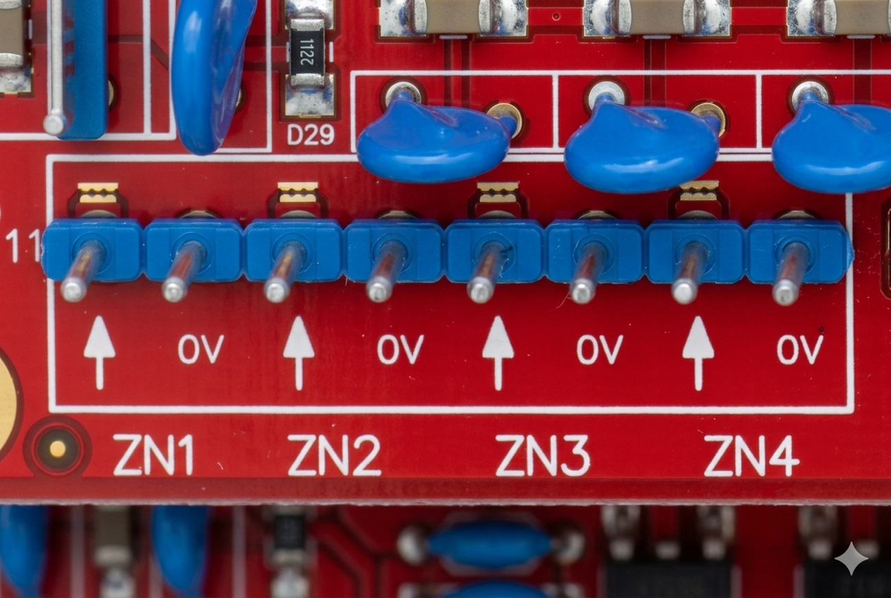
Board Layout
Terminal Pinouts
Power Connections (T4 & T6)
| Terminal | Label | Function | Connection Notes |
|---|---|---|---|
| T4 | AC IN | 24V DC or 16-18V AC Input | From AC-DC Adapter, Transformer Secondary, or Plug Pack output. See wiring diagrams on pages 4-5 of the Installation Manual. |
| T6 | BATTERY | Battery Connection | Polarized connector. Red wire to Battery (+), Black wire to Battery (−). 5A Fast Blow fuse (F1a, non-replaceable). |
NOTE
The ISC has onboard power supply circuitry with direct screw/clamp terminals for AC/DC input and battery. Unlike LAN modules (SLAM, ILAM, IAC, 8-Zone Expander), it does not require a 10-pin power cable.
RS485 Sub-LAN (T2 & T3)
| Terminal | Label | Function | Connection Notes |
|---|---|---|---|
| POS | +13.75V | LAN Power (+) | Power supply for LAN Modules/Readers (2A Limit). |
| 0V | 0V | LAN Power (-) | Reference Ground. |
| A | A | RS485 LAN A | Data A (Standard: White Wire). |
| B | B | RS485 LAN B | Data B (Standard: Blue Wire). |
Auxiliary Relays (T5)
| Terminal | Label | Function | Connection Notes |
|---|---|---|---|
| AUX1 | C/NO/NC | Aux Relay 1 | General purpose SPDT Relay (30V DC / 1A). |
| AUX2 | C/NO/NC | Aux Relay 2 | General purpose SPDT Relay (30V DC / 1A). |
On-board Zones (T11 - T14)
| Block | Terminals | Function | Connection Notes |
|---|---|---|---|
| T11 | Z1 - Z4 | Zones 1-4 | 4 Multistate Inputs + Common 0V. |
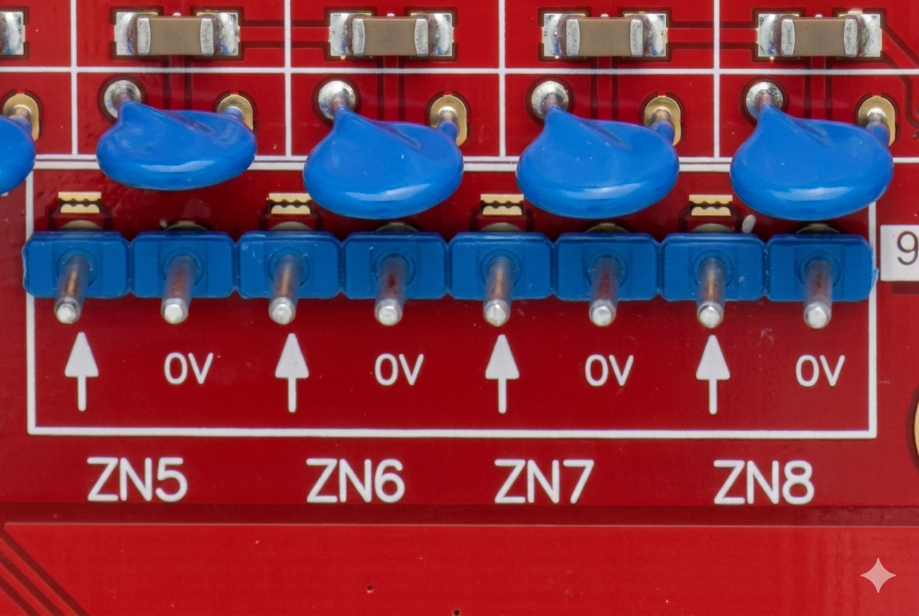
| T12 | Z5 - Z8 | Zones 5-8 | 4 Multistate Inputs + Common 0V. |
| T13 | Z9 - Z12 | Zones 9-12 | 4 Multistate Inputs + Common 0V. |
| T14 | Z13 - Z16 | Zones 13-16 | 4 Multistate Inputs + Common 0V. |
| Note | EOL | End-of-Line | Default: 2k2 Series / 2k2 Parallel. |
Wiring Diagrams
RS485 LAN Sub-LAN Wiring (Standard Daisy-Chain)
graph LR
    subgraph "ISC Controller (T2/T3)"
        ISC_A[A]
        ISC_B[B]
        ISC_POS[POS]
        ISC_NEG[0V]
    end

    subgraph "SIFER Reader (Sub-LAN)"
        SR_A[A]
        SR_B[B]
        SR_POS[+V]
        SR_NEG[0V]
    end

    subgraph "ILAM / SLAM (Sub-LAN)"
        MOD_A[A]
        MOD_B[B]
        MOD_POS[POS]
        MOD_NEG[0V]
    end

    %% Connections
    ISC_A --- SR_A
    SR_A --- MOD_A

    ISC_B --- SR_B
    SR_B --- MOD_B

    ISC_POS --- SR_POS
    SR_POS --- MOD_POS

    ISC_NEG --- SR_NEG
    SR_NEG --- MOD_NEG
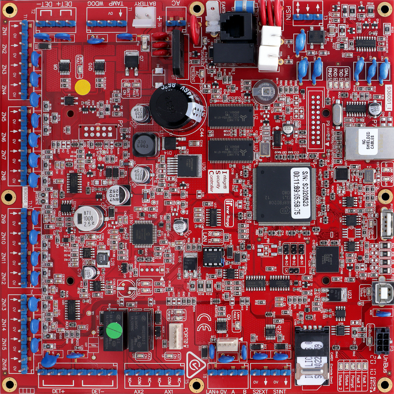
Standard Detector Power Wiring (Common)
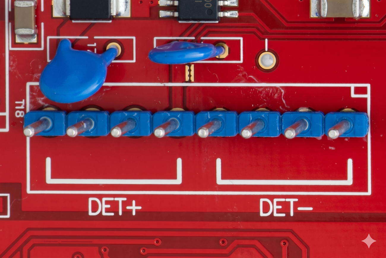
Standard Auxiliary Relay Wiring (Common)
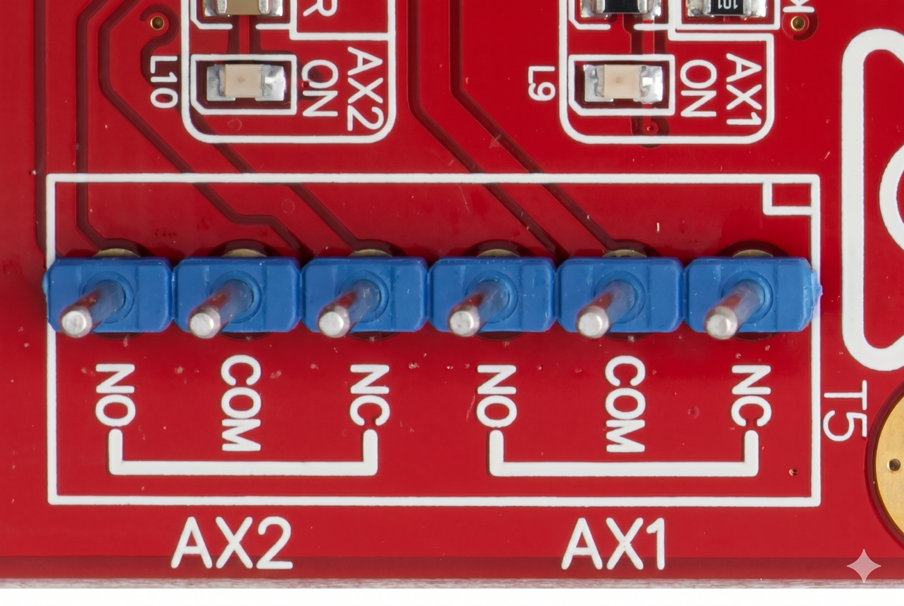
Standard Zone Wiring (Common)
Note: These diagrams apply to all onboard zone blocks (T11-T14).
Configuration / Programming
- Addressing: Managed via Integriti software.
- Firmware: Upgradable via USB, LAN, or Software.
- Memory: 32 Bit ARM with Real Time Clock, 64 MB RAM. Rev G+ (2018+) uses on-board flash memory for database and review log. Pre-Rev G controllers used Micro SD.