Inception Controller
Overview
The Inception Controller is a web-powered security system that integrates Intruder Detection, Access Control, and Automation into a single, easy-to-use solution. It features a built-in web interface for “Zero-Software” management.
Key Specifications
User Capacity : 10,000.Event Log : 250,000 events.Doors : 4 on-board (expandable to 128 via LAN).Areas : 96.Connectivity : Built-in Ethernet, optional Wi-Fi (via USB adapter), and SkyTunnel support.
Physical I/O
Inputs : 8 Universal Zone Inputs (expandable to 1024).Outputs : 4 Universal Relay Outputs (expandable to 1024; 5A 30V DC/AC rating).Readers : 1 RS485 LAN OSDP Reader bus (supports up to 8 SIFER/OSDP readers directly).Expansion : UniBus port for local I/O; RS485 LAN port for remote modules.
Power Requirements
Recommended Input : 18V to 24V DC 2.5A (via DC IN).Alternate Input : 12.8V-14V DC 2.8A (via BATT connection).Battery : Supports 12V SLA (7AH to 18AH).Idle Current :
DC IN (24V): 60mA (85mA with Ethernet).
BATT (12V): 110mA (150mA with Ethernet).
Relay Current : 25mA per active relay (33mA when powered from BATT).Battery Charger : 13.75V DC, up to 500mA charging current.Low Battery Alarm : 11.0V DC.Deep Discharge Protection : Activates at 10.4V, restores at 12.5V.Typical Backup (Ethernet + 1 LCD Terminal + 200mA load): 16 hrs (7AH) / 40 hrs (18AH).Typical Recharge : 18 hrs (7AH) / 42 hrs (18AH).Battery Input Fuse : 7A, non-replaceable.
Compatible Firmware
All-in-one system; check [System > Service] for current firmware updates.
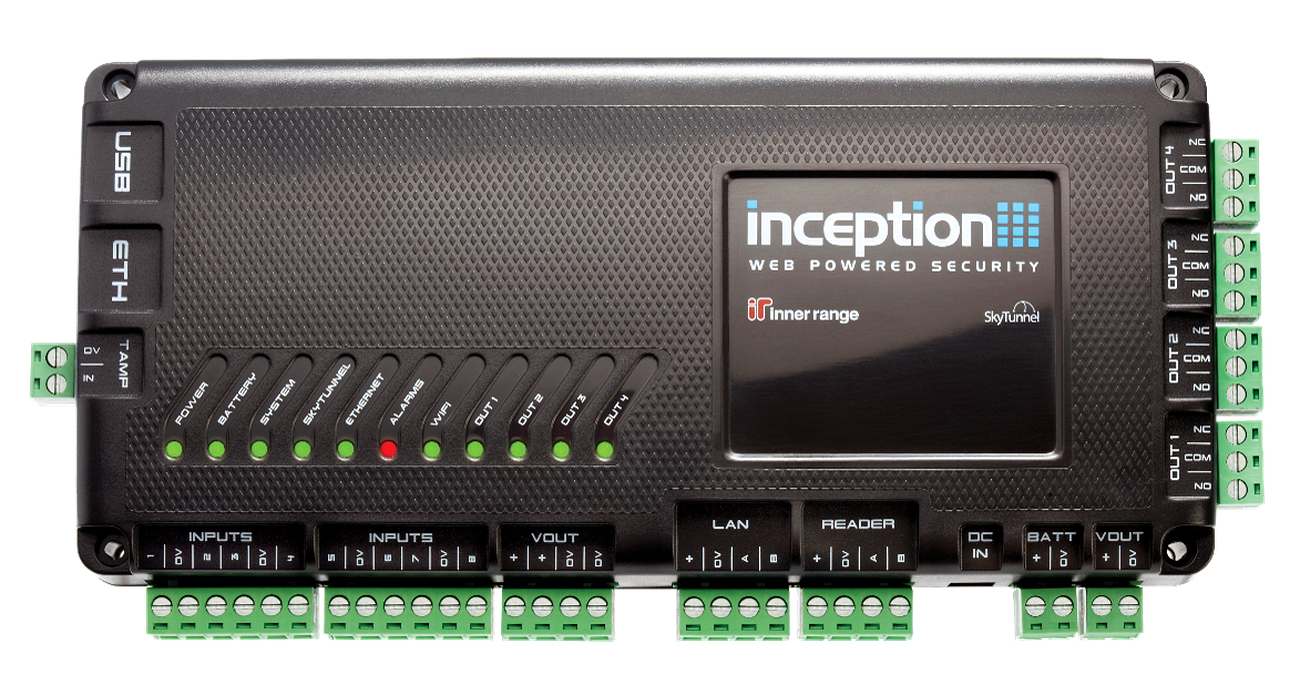
Board Layout
Terminal Pinouts
Power (T1 & P1)
Block Label Function Connection Notes P1 DC IN Power Input (+) 18-24V DC / 2.5A. P1 DC IN Power Input (-) Reference Ground. T1 BATT+ Battery Pos Red lead to 12V SLA Battery. T1 BATT- Battery Neg Black lead to 12V SLA Battery.
RS485 LAN (T2)
Terminal Label Function Connection Notes T2.1 +12V LAN Power (+) Power for LAN Expanders (1A Limit). T2.2 0V LAN Power (-) Reference Ground. T2.3 A RS485 LAN A Data A. T2.4 B RS485 LAN B Data B.
Relays 1-4 (T5 - T8)
Block Label Function Connection Notes T5-T8 LCK1-4 Relay Output Switched Output (5A @ 30V DC/AC). T5-T8 C1-4 Relay Common Common terminal for Relay 1-4.
Block Label Function Connection Notes T11 Z1-Z4, 0V Inputs 1-4 4 Configurable Inputs + Common 0V. T12 Z5-Z8, 0V Inputs 5-8 4 Configurable Inputs + Common 0V. Note EOL End-of-Line Standard: 2k2 Series / 2k2 Parallel .
Device Power (T15)
Terminal Label Function Connection Notes T15.1 VOUT 12V DC Out (+) Supply for Detectors/Readers (1A Limit). T15.2 0V 12V DC Out (-) Reference Ground.
Wiring Diagrams
Door Lock Wiring (Inception Relay 1)
graph LR
    subgraph "Inception Controller"
        INC_C1[C1]
        INC_L1[LCK1]
        INC_VOUT[VOUT]
        INC_GND[0V]
    end

    subgraph "Lock"
        LOCK[Electric Strike]
        DIODE{{1N4004 Diode}}
    end

    %% Wiring
    INC_VOUT ==> INC_C1
    INC_C1 ==> INC_L1
    INC_L1 ==> LOCK
    LOCK --- DIODE
    LOCK ==> INC_GND
Related Pages
This is an unofficial, community-maintained reference wiki. It may lag behind official documentation and is not guaranteed to be accurate or complete. Inner Range is a registered trademark of Inner Range Pty Ltd. This site is not authorized, endorsed, or affiliated with Inner Range. Always cross-reference technical details with the official documentation at www.innerrange.com.
Created with Quartz v4.5.2 © 2026