Switched DC Power Hub
Compliance Note: Fire Alarm Integration
Under the National Building Code (NBC), access-controlled doors in egress paths must release automatically upon fire alarm activation to allow safe evacuation. The Switched DC Power Hub facilitates this mandatory fail-safe operation by dropping power to the locks when the fire alarm panel triggers.
Overview
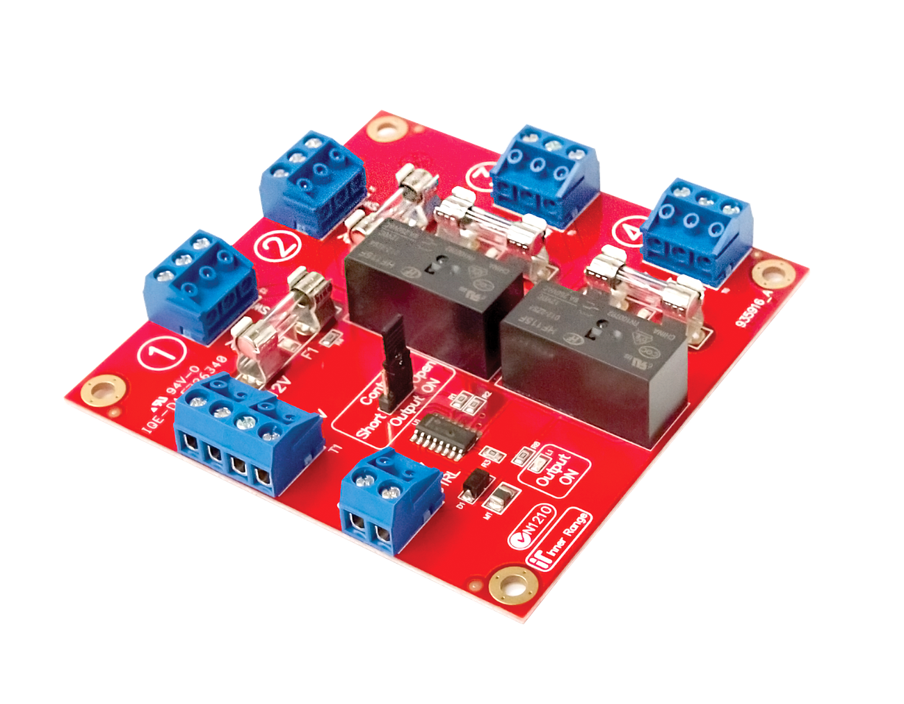
The Switched DC Power Hub (P/N: 995916) is a critical life-safety integration module. Its primary purpose is to interface the access control system with a building’s fire alarm or emergency evacuation system. It provides four separately fused power outputs that can be globally switched off in response to a fire alarm signal, dropping power to fail-safe locks (like magnetic locks) to ensure unimpeded egress.
Technical Details
Power Specifications
- Input Voltage: 11V to 14V DC (provided by the host Smart Power Supply).
- Current Consumption: 95mA when the output is “On” (idle, no load).
- Output Capacity:
- 4 independent output channels.
- Max current per channel: < 2A (protected by 2A Fast Blow fuses: F1, F2, F3, F4).
- Important: The total current drawn across all four outputs must not exceed the maximum capacity of the host power supply.
Output Types
Each of the 4 output channels provides two types of DC connections:
- Unswitched (
OUT): Provides constant 12V DC power (e.g., for powering readers or secure-side devices). - Switched (
OUTSW): Drops power based on the state of the Control Input. Used for fail-safe locks.
Control Input
A single Control Input determines the state of all four OUTSW connections.
- Control Modes (LK2):
- Contact: Triggered by voltage-free dry contacts from the Fire Panel.
- 12V-24V: Triggered by the presence/absence of a DC voltage (Switching threshold: 2V).
- Active State (LK1): Configures whether the
OUTSWis energized when the input is Short/0V or Open/12V-24V.
Feedback and Monitoring
- Relay Feedback (T7): Provides a relay output (Max 2A @ 30VDC) to signal the current state of the switched outputs back to the Integriti/Inception controller for monitoring and reporting.
- LED Indicators:
- L1 (Output ON): Indicates the
OUTSWterminals are energized. - L2-L5: Fuse blown indicators (only visible if a load is connected).
- L1 (Output ON): Indicates the
Board Layout
Terminal Pinouts
Power Input (T1)
| Terminal | Label | Function | Connection Notes |
|---|---|---|---|
| T1 | +12V / 0V | Power Input | Connect to host Power Supply output (e.g., Integriti 8A or 10A Smart PS). Extra terminals allow additional conductors for increased current capability. |
Control Input (T2)
| Terminal | Label | Function | Connection Notes |
|---|---|---|---|
| T2.1 | CTRL | Control Input | Fire Panel Trigger (Contact or 12V-24V). |
| T2.2 | 0V | Input Common | Reference ground. |
Feedback Relay (T7)
| Terminal | Label | Function | Connection Notes |
|---|---|---|---|
| T7.1 | C | Relay Common | Feedback to Controller (Max 2A @ 30V DC). |
| T7.2 | NC | Relay N/C | Closed when Outputs are ON (Revision C). |
| T7.3 | NO | Relay N/O | Open when Outputs are ON (Revision C). |
NOTE
On Revision B PCBs (manufactured 2014-2016), the NC and NO terminals are swapped. Verify PCB revision before wiring.
DC Outputs (T3 - T6)
| Terminal | Label | Function | Connection Notes |
|---|---|---|---|
| T(n).1 | 0V | Common (-) | Return path for locks/devices. |
| T(n).2 | OUT | Unswitched DC (+) | Continuous 12V-14V DC (2A Fuse). |
| T(n).3 | OUTSW | Switched DC (+) | Fail-Safe Lock Power (Switched by T2). |
n = 3, 4, 5, 6 for Outputs 1 through 4 respectively.
Installation & Wiring
- Mounting: Can be installed in an Inner Range enclosure using PCB mounting clips.
- Lock Wiring:
- Normally Energized (Fail-Safe): Wire locks to the
OUTSWterminals. The control link must be configured so that a fire alarm event de-energizes this output. - Important: If the lock is inductive, clamp diodes (e.g., 1N4004) must be fitted at the lock.
- Normally Energized (Fail-Safe): Wire locks to the
- Host Connection: Typically powered directly from an Integriti 8A or 10A Smart Power Supply to handle the high current demands of multiple magnetic locks.