Intelligent LAN Access Module (ILAM)
Overview
The Intelligent LAN Access Module (ILAM) is an 8-door capable access control module for the Integriti platform. It features offline intelligence with a large user and event database, ensuring operation even when disconnected from the master controller.
Platform Identification:
- Integriti: Identified as an 8-Door Reader Module (I).
Technical Details
Capacity and Integration
- Doors/Readers: 2 doors/lifts on-board. Expandable to 8 doors via UniBus 2-Door Expanders.
- Reader Support: Supports up to 16 SIFER/OSDP readers or 2 Wiegand readers (on-board).
- Offline Cache: 100,000 Users and 100,000 events.
- Wireless Lock Support: Supports Aperio, SimonsVoss, and SALLIS wireless locks. Each OEM requires its own hub connected to the ILAM’s RS485 LAN reader port (locks paired to hub via OEM programming app). SALLIS requires a Salto SALLIS 8 Door Interface hub (up to 8 locks per ILAM). Aperio supports up to 8 hubs. See Wireless Door Integration.
UniBus Expansion Options
Connector P2 on the ILAM is the UniBus port. A maximum of 6 UniBus boards can be connected in total, subject to the following limits:
| UniBus Board Type | Max Boards | Description |
|---|---|---|
| 2-Door Expander | 3 | Extends ILAM to its maximum of 8 doors. |
| 8-Relay Expander | 1 | Assigned to Auxiliaries 9-16. |
| 16-Floor Lift Expander | 6 | Supports up to 96 floors per ILAM. |
Electrical Specifications
- Power Input: 11V to 14V DC (Smart PSU highly recommended for UniBus expansion).
- Current Consumption:
- Idle: 110mA.
- Both Lock Relays On: 175mA.
- Both Lock & DOTL Relays On: 200mA.
- Ancillary Output Limit: 1.2A maximum total (combined for DET+, UniBus, LAN+, V+, +VR1 & +VR2).
- Reader Power (T4/T7): 250mA maximum per output (each independently PTC protected).
- Relay Contact Ratings:
- LOCK Relays: 5A @ 30V DC.
- DOTL Relays: 1A @ 30V DC (Normally-open Dry Contacts).
- VAL/INV Outputs: Open Collector, 100mA @ 13.75V DC (non-inductive loads only).
- Lock Power Input (T10): 30V DC maximum (dedicated input for Lock +/- terminals; must be power-limited/fused and battery-backed).
Physical I/O and Relays
Integriti Relay & Output ID Mapping
The ILAM on-board relays and UniBus expander relays are mapped as follows (where nn:X is the module address):
| Component | Door / Reader | LOCK Relay | DOTL Relay |
|---|---|---|---|
| ILAM On-board | Door 1 | Inn:X01 | Inn:X09 |
| ILAM On-board | Door 2 | Inn:X02 | Inn:X10 |
| UniBus 1 (D1) | Door 3 | Inn:X03 | Inn:X11 |
| UniBus 1 (D2) | Door 4 | Inn:X04 | Inn:X12 |
| UniBus 2 (D1) | Door 5 | Inn:X05 | Inn:X13 |
| UniBus 2 (D2) | Door 6 | Inn:X06 | Inn:X14 |
| UniBus 3 (D1) | Door 7 | Inn:X07 | Inn:X15 |
| UniBus 3 (D2) | Door 8 | Inn:X08 | Inn:X16 |
Physical Specifications
- PCB Dimensions: Length 200mm (7.9”) × Width 94mm (3.7”) × Depth 45mm (1.8”).
- Operating Environment: 0°C to 70°C (32°F to 158°F), 15% to 90% Relative Humidity (non-condensing).
- Firmware Compatibility: ISC/IAC Firmware V3.0 or later. Integriti Software V3.0 or later (latest versions recommended).
Configuration / Programming
Status and Fault LEDs
| LED | Name | Indication |
|---|---|---|
| L1 | RX | Valid LAN packet received. Also used for LAN/System fault indication (see fault table below). |
| L2 | TX | LAN packet transmitted. Also used for LAN/System fault indication (see fault table below). |
| L3 | FAULT | ON = LAN fault (see L1/L2 table). FLASHING + L1 FLASHING = Hardware fault (return for repair). FLASHING + L2 FLASHING = Firmware fault (return for repair). |
| L4 | SYS | ON = Module starting up. FLASHING = Module powered and firmware running correctly. |
| L5/L6 | D0/D1 | Reader Data Receive indication for both on-board Reader Inputs. |
| L10/L11 | RX/TX | Reader RS485 LAN port (T1) data receive and transmit indication. |
| L12/L13 | eFuse | Indicates over-current fault on +VR1 or +VR2. |
| L14 | UniBus | FLASHING = Idle (no UniBus boards connected). OFF = OK (UniBus boards communicating). ON = Fault (e.g. address conflict). |
| L16/L17 | Lock | Lock 1 / Lock 2 Relay On indication. |
LAN Fault Code Table (L1/L2)
| L1 | L2 | Explanation / Remedy |
|---|---|---|
| ON | ON | Module is un-addressed (not communicating with Controller). |
| ON | OFF | Too many modules on the network. Check limits and licensing. |
| OFF | ON | Module type unknown. Controller firmware upgrade required. |
| Flash | ON | Duplicate Module address. Number already in use by module of same type. |
| Flash | Flash | Module number selected is too high. Select a lower number or check limits and licensing. |
| ON | Flash | Module disabled (OFF/Flash in earlier firmware versions). |
- Firmware Update Memory Erase: If memory needs to be erased after an update, LEDs L1/L2/L3 will be OFF and L5/L6 will be ON (may take up to 1 minute).
Board Layout
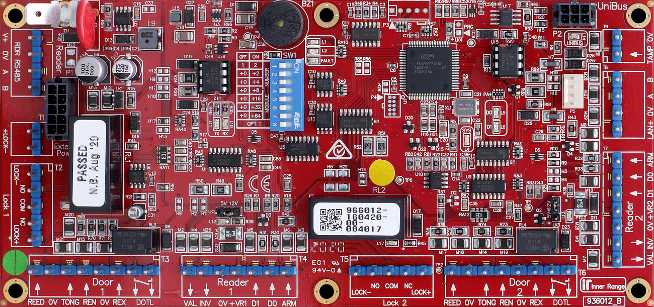
Terminal Pinouts
Critical: 10-Pin Power Requirement
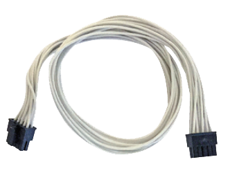
This module does not have screw terminals for main power input. It requires a specialized 10-pin power cable connected to the on-board power header:
- P/N 996792: For connection to an Inner Range Smart PSU.
- P/N 996794: For connection to a 3rd Party PSU (Standard DC Input).
LAN Input (T2)
| Terminal | Label | Function | Connection Notes |
|---|---|---|---|
| T2.1 | POS | LAN Power (+) | 11V-14V DC Input. |
| T2.2 | 0V | LAN Power (-) | Reference Ground. |
| T2.3 | A | RS485 LAN A | Data A. |
| T2.4 | B | RS485 LAN B | Data B. |
Door 1 Control (T3)
| Terminal | Label | Function | Connection Notes |
|---|---|---|---|
| T3.1 | LOCK1 | Lock 1 Output | Connect to Lock Pos (+). Fit Diode. |
| T3.2 | DOTL1 | Door Open Alert | Connect to Buzzer/LED (+). |
| T3.3 | REED1 | Door Contact In | Connect to Reed Switch. Requires 2k2/2k2 EOL. |
| T3.4 | TONGUE1 | Tongue Sense | Optional tongue sense input. Requires 2k2/2k2 EOL. |
| T3.5 | REX1 | Request to Exit | Connect to Exit Button. Requires EOL. |
| T3.6 | REN1 | Request to Enter | Connect to Entry Button. Requires EOL. |
| T3.7 | 0V | Common (-) | Common Ground for Door 1. |
Reader 1 Power & Data (T4)
| Terminal | Label | Function | Connection Notes |
|---|---|---|---|
| T4.1 | +V | Reader Power (+) | 12V DC Supply (250mA per output limit). Voltage selectable via LK2: 5V or 13.75V. |
| T4.2 | 0V | Reader Power (-) | Reference Ground. |
| T4.3 | VAL1 | Valid Output | Open Collector (100mA). Connect to Reader LED/Beeper. |
| T4.4 | INV1 | Invalid Output | Open Collector (100mA). Connect to Reader LED/Beeper. |
Wiegand Reader 1 (T5)
| Terminal | Label | Function | Connection Notes |
|---|---|---|---|
| T5.1 | D0 | Data 0 | Reader Data 0. |
| T5.2 | D1 | Data 1 | Reader Data 1. |
| T5.3 | LED | LED Control | Reader LED control. |
| T5.4 | BZ | Buzzer Control | Reader Buzzer control. |
| T5.5 | 0V | Common (-) | Reader Ground. |
Door 2 & Reader 2 (T6 - T8)
| Block | Type | Function | Notes |
|---|---|---|---|
| T6 | Door 2 | LCK/DOTL/REED/TONG/REX/REN | Duplicate of Door 1 logic (includes Tongue Sense). |
| T7 | Reader 2 | +V/0V/VAL2/INV2 | Duplicate of Reader 1 Power & VAL/INV. Voltage via LK3. |
| T8 | Wiegand 2 | D0/D1/LED/BZ/0V | Duplicate of Wiegand 1. |
Reader Voltage Selection
- LK2 (Reader 1) and LK3 (Reader 2) select between 5V and 12V (13.75V) for reader power on +VR1/+VR2.
- Recommendation: Use 5V for readers with wide voltage ranges unless 12V is required for maximum read range.
Input Device Supervision
- Door Reed / Tongue Sense: Must be supervised using EOL resistors (standard is 2k2/2k2).
- REX / REN: EOL resistors optional (standard is 2k2/2k2). A Module programming option (“Override EOL”) allows REX/REN to be wired without EOL if permitted (default option).
- ARM Input: Does not require EOL resistors.
- Normally Open Contacts: When programming NO alarm contacts, the “Swap Alarm and Seal” option must be set to [Y]es.
Wiring Diagrams
OSDP Reader Wiring — RDR RS485 LAN Port (T1)
Transclude of assets/diagrams/osdp-reader-wiring-ilam.excalidraw
View online: excalidraw.com
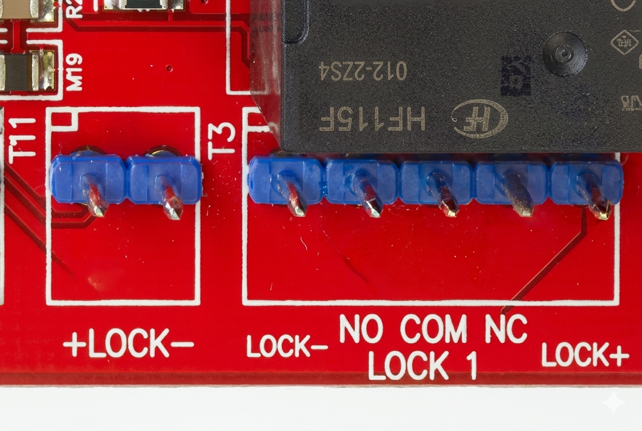
Standard Lock Relay Wiring (Common)
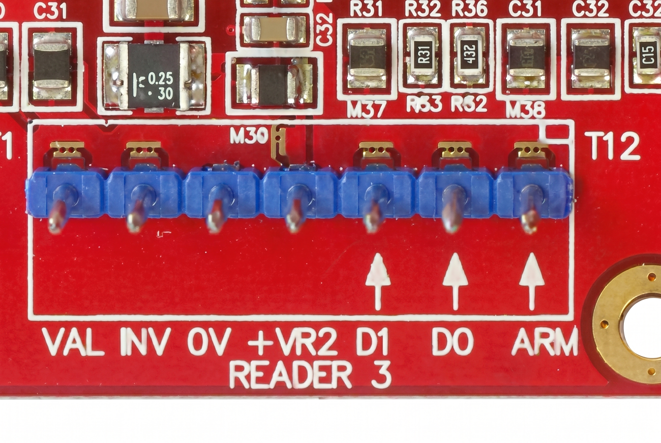
Standard Wiegand Reader Wiring (Common)
Door 1 Wiring (ILAM)
Transclude of assets/diagrams/ilam-door1-wiring.excalidraw