LAN Ethernet Bridge Module
Overview
The LAN Ethernet Bridge (P/N: 996088) provides a secure, isolated connection of physically separate RS485 LAN segments over an Ethernet network. It eliminates the need for long RS485 LAN cable runs by leveraging existing IP infrastructure, and provides electrical isolation between LAN segments to eliminate earth loops.
Technical Details
- Security: 128-bit AES encryption for Ethernet communications.
- Protocols: Supports both TCP (default) and UDP. UDP may improve reliability if network issues are encountered.
- System Enrollment: Enrolls on the LAN as an RS485 LAN Module for status monitoring. In Integriti/Infiniti systems, it enrols as a type ‘P’ Module.
- Management: Field upgradeable firmware and configurable via the Ethernet LAN Configuration Tool or the Installer Serial Console (Port 0).
System Limits
- Bridges per Controller: Up to 30.
- Modules per Bridge: Up to 30 RS485 LAN modules downstream.
- Total LAN Modules via Bridges (varies by system type and protocol):
| System Type | TCP Limit | UDP Limit |
|---|---|---|
| Intruder Alarm Only | 90 | 120 |
| Access Control (No ILAM) | 60 | 90 |
| Large/Busy Integrated (With ILAM) | 30 | 45 |
Board Layout
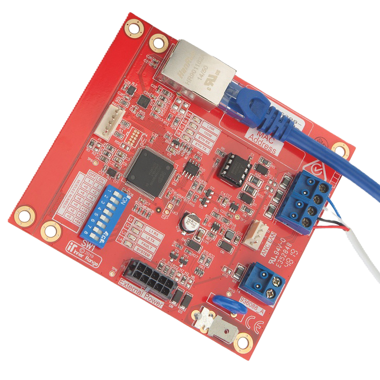
Terminal Pinouts
Power and LAN (T1)
| Terminal | Label | Function | Connection Notes |
|---|---|---|---|
| T1.1 | POS | Power Input (+) | 11V-14V DC Input. |
| T1.2 | 0V | Power Input (-) | Reference Ground. |
| T1.3 | A | RS485 LAN A | Data A. |
| T1.4 | B | RS485 LAN B | Data B. |
Ethernet Port (P1)
| Port | Type | Function | Notes |
|---|---|---|---|
| P1 | RJ45 | Ethernet | 10/100 Mbps (Shielded Cat5e/6 recommended). |
Configuration / Programming
IP Addressing
Supports both DHCP and Static IP allocation. Configure prior to installation using the Ethernet LAN Configuration Tool software.
Controller Linking
- Linking Code: Obtain a connection code from the Controller’s management interface (SkyTunnel for Inception, or System Designer for Integriti).
- Encryption Key: A 32-character hexadecimal key (or passphrase) must match between the Controller and the Bridge.
- Port: Uses Port 40844 for connection to SkyTunnel.
Installer Serial Console (Port 0)
Local configuration via the P1 (Port 0) connector using a Port 0 cable (993030USB) and a terminal program (115200 baud, 8, N, 1).
Minimum Firmware
- Integriti/Infiniti: V20.1.
- Inception: V4.0.
Installation & Wiring
Power Requirements
The Bridge must be powered from a battery-backed 11-14V DC source:
- LAN Connection: Via the 4-wire RS485 LAN (LAN+/0V).
- Smart Power Supply: Via the 10-way PSU bus cable (P3).
- General PSU: Via the PSU Cable (P/N: 996794).
Wiring Rules
- RS485 LAN Port (T1): Must NOT be connected to another Bridge’s RS485 LAN port or directly to a Controller’s RS485 LAN port.
- Cable Type: Standard 10/100 Mbps Ethernet for the IP side; Shielded twisted-pair for the RS485 LAN side.
- Mounting: Must be installed in a tamper-monitored enclosure.
Specifications
- Input Voltage: 11-14V DC.
- Operational Current: 60mA.
- Installation Environment: 0°C to 49°C (32°F to 120°F), 15% to 85% Relative Humidity (non-condensing).
- Ethernet: 10/100 Mbps.
- Physical Dimensions: 105mm (L) x 94mm (W) x 18mm (H). 94mm x 94mm with snap-off mounting strip removed. Allow 40mm clearance above PCB if the 10-way PSU cable is connected.
Recommended Enclosures
- 995200PE3: Small, powered enclosure with 3A Smart PSU.
- 995200PE2: Small, powered enclosure with 2A Std PSU.
- 995200XS: Extra small, unpowered enclosure.
- 995200: Small, unpowered enclosure.
- Existing tamper-monitored enclosure housing an RS485 LAN Module.
LED Indicators
- SYSTEM (L4): Slow Flash = OK; Fast Flash = Internal Fault.
- FAULT (L3): Indicates LAN or System faults. See diagnostic table below.
- LINK (L5): Ethernet connection status. ON = Link present. Flash = Network activity.
- 100M (L6): ON = 100Mbps; OFF = 10Mbps.
- L1/L2: RS485 LAN RX/TX data activity.
- L7/L8: ETH RX/ETH TX — Ethernet traffic indication (flickering = active).
FAULT LED (L3) Diagnostics
When the FAULT LED (L3) is ON, L1 and L2 indicate the problem type:
| L1 | L2 | Fault | Remedy |
|---|---|---|---|
| OFF | ON | UNKNOWN | Module type unknown. Controller firmware upgrade required. |
| ON | OFF | NO ROOM | Too many Modules on the network. Check limits and licensing. |
| ON | ON | NO ADDRESS | Module un-addressed (not communicating with Controller). |
| ON | FLASH | DISABLED | Module is disabled. |
| FLASH | OFF | CONT/BRIDGE | Another Bridge or Control Module connected to RS485 port. Check cabling. |
| FLASH | ON | EXISTS | Duplicate Module number. |
| FLASH | FLASH | DIMENSION | Module number too high. Select a lower, unused number. |
When L3 is SLOW FLASHING:
- L1 Flashing / L2 OFF: System Fault (Hardware). Return for repair.
- L1 OFF / L2 Flashing: System Fault (Firmware). Return for repair.
When L3 is FAST FLASHING: DIPswitch reset pending.
DIPswitch Configuration (SW1)
The Module number is set using DIPswitches 1–5 on SW1. The Module number = n + 1, where n is the binary value set on the DIPswitches.
| DIPswitch | 1 | 2 | 3 | 4 | 5 |
|---|---|---|---|---|---|
| Binary Value | 1 | 2 | 4 | 8 | 16 |
Factory Reset Procedures:
- DIP 1-7 ON: Reset all settings to factory defaults EXCEPT the Encryption Key.
- All DIPswitches ON: Reset ALL settings to factory defaults.
- Procedure: Disconnect power → set DIPswitches → reconnect power → wait 5 seconds → disconnect power → restore normal DIPswitch settings → reconnect power.
Integriti/Infiniti System Inputs
The LAN Ethernet Bridge uses 10 of 16 allocated System Inputs:
| Input | Function | Input | Function |
|---|---|---|---|
| Pnn:S01 | Cabinet Tamper | Pnn:S09 | RS-485 LAN Comms Fault* |
| Pnn:S02 | AC Fail | Pnn:S13 | Low Volts |
| Pnn:S03 | Low Battery | Pnn:S14 | PS Fail |
| Pnn:S05 | Detector Fuse | Pnn:S15 | Battery Test Fail |
| Pnn:S06 | LAN Fuse | Pnn:S16 | LAN Comms Fail |
* Pnn:S09 alarm = Control Module or another Bridge connected to RS485 LAN Port (T1). (Monitored in firmware V1.0.6+)
Ancillary Connections
- P5 (ANC LAN): Ancillary LAN connection for temporary LCD/EliteX Terminal connection via Ancillary LAN Cable (P/N: 993028).
- T4 (TAMP/0V): Cabinet Tamper Input.
- P3 (External Power): External Power Supply Input via Smart PSU Bus Cable or PSU Cable (P/N: 996794).
When to Use
- RS485 LAN Limitations: When standard RS485 LAN cabling (1500m limit) is difficult or impossible to run.
- Structured Cabling: To leverage existing building Ethernet infrastructure.
- Earth Loop Mitigation: To electrically isolate segments in complex sites.
- Legacy Support: Supports legacy Concept 3000/4000 LAN modules.
Troubleshooting
- Voltage Check: LAN +ve to GND should be 11V to 14V DC.
- Module Offline: Verify encryption keys match between Bridge and Controller.
- LAN Secure: After adding modules, always perform a “LAN Secure” operation from the Controller software.
- LAN Poll Time: Unless local regulations require otherwise, keep the default 1-minute
LAN Poll Time. Short poll times (<10s) significantly increase LAN traffic. - Encryption Key Formats: The key can be set as a 32-character hex string OR an alpha-numeric passphrase. If the Controller is defaulted, it reverts to the default (all-zeros) key.