Fibre Modems
Overview
The Fibre Modem provides two separate, optically isolated ports for the Inner Range RS485 LAN. It is used to extend LAN distance, provide immunity to earth loops, and protect against lightning strikes and electrical noise. Part numbers: 995081 (Multimode), 995087 (Single Mode).
Multi Mode
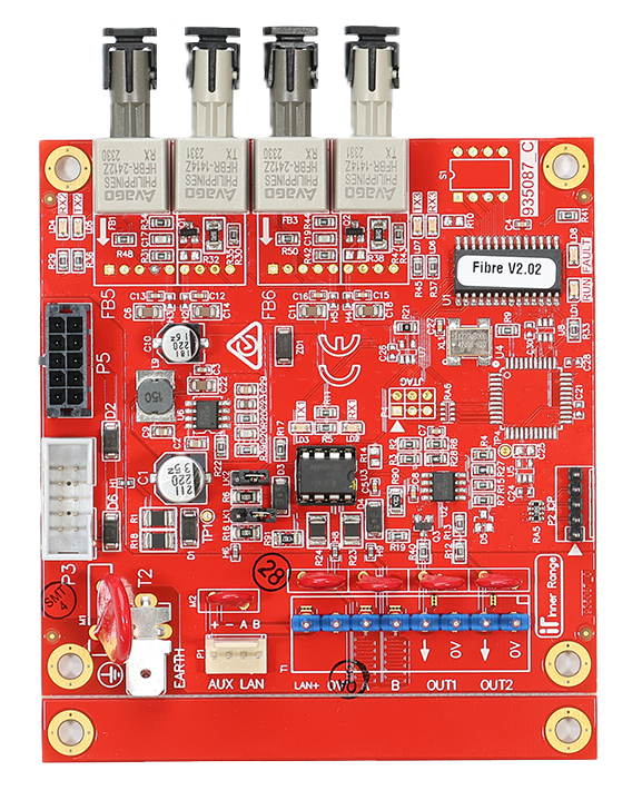 Single Mode
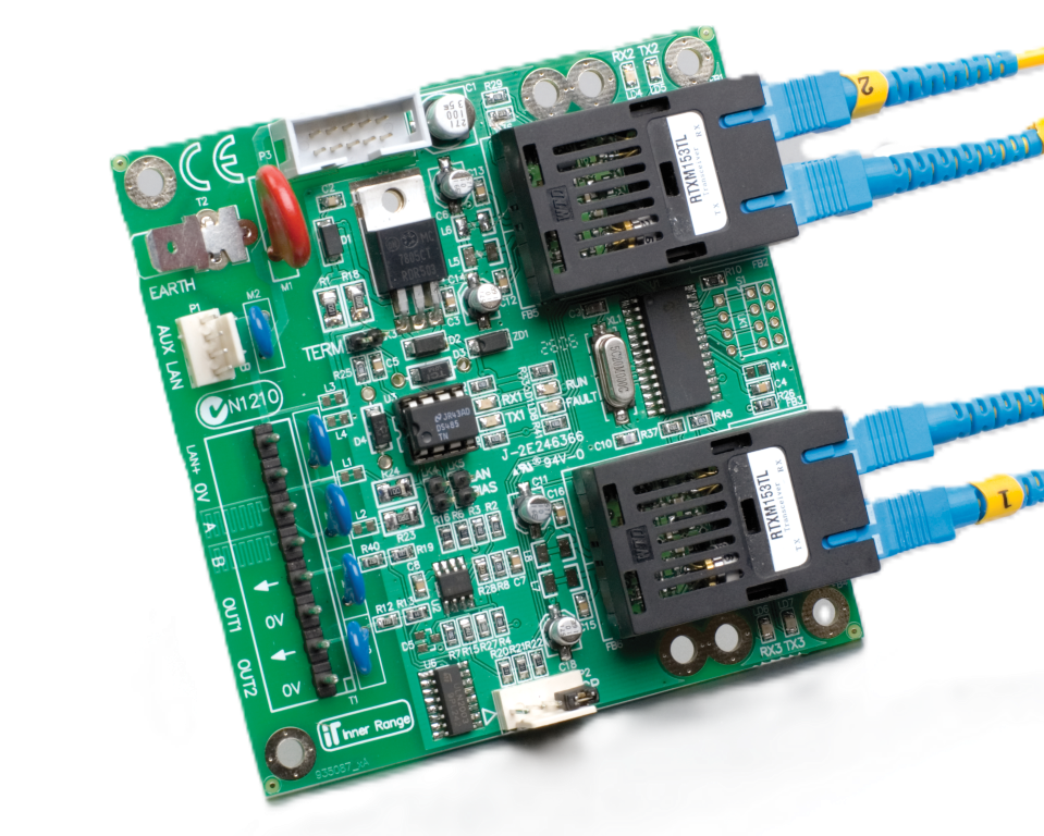
Technical Details
- Connectivity: Two fibre ports allowing ‘branch’ or ‘loop’ configurations.
- Distance Extension:
- Multimode: Up to 3km (62.5/125µm 850nm cable, Type ST connectors).
- Single Mode: Up to 13km (9/125µm 1300nm cable, Type SC connectors).
- Series Connection: Limited by delay unit budget (max 15 delay units between any two modules). Practical examples show up to 8 modems in a daisy-chain.
- Isolation: Optical isolation provides electrical separation between LAN segments.
- Fault Reporting: ‘Loop Fault’ and ‘Branch Fault’ auxiliary outputs for monitoring.
- Installation Environment: 0°C to 50°C (32°F to 122°F), 15% to 85% Relative Humidity (non-condensing). Indoor use only.
- Physical Dimensions: 105mm (L) x 94mm (W). 94mm x 94mm with snap-off strip removed. Fibre connector head protrudes 15mm from PCB.
- Fault Timeout: Outputs go into alarm after 255 seconds of no data received on the optical port.
Terminal Pinouts
LAN and Power (T1)
| Terminal | Label | Function | Connection Notes |
|---|---|---|---|
| T1.1 | POS | Power Input (+) | 11V-14V DC Input. |
| T1.2 | 0V | Power Input (-) | Reference Ground. |
| T1.3 | A | RS485 LAN A | Data A. |
| T1.4 | B | RS485 LAN B | Data B. |
Fault Monitoring (T2)
| Terminal | Label | Function | Connection Notes |
|---|---|---|---|
| OUT1 | C / NO | Port 1 Fault | Closes on Fibre 1 signal loss. |
| OUT2 | C / NO | Port 2 Fault | Closes on Fibre 2 signal loss. |
Configuration / Programming
- LAN Bias Links: Modems connecting to remote Modules MUST have LAN Bias Links (LK1 & LK2) fitted. Modems connecting directly to a Control Module, a LAN Isolator, or another Fibre Modem (that already has links) must NOT have them fitted.
- Monitoring:
OUT1andOUT2can be wired to Zone Inputs to monitor fibre optic status (e.g., Data Not Detected in Port 1 or 2). - Ancillary LAN (P1): Provides a temporary connection for an LCD/EliteX Terminal when required.
- Network Design (Delay Units):
- Fibre Modems introduce signal delay. System design must calculate “Delay Units”.
- Maximum 15 Delay Units between any two modules (or 14 for a fibre loop).
- Calculation: 1 Unit per Fibre Modem + 1 Unit per 1km of Fibre Cable + 1 Unit per 1.35km of twisted pair LAN cable.
- Modems are transparent to the RS485 LAN protocol but provide physical layer isolation and extension.
- Supports redundant LAN paths when used in a ‘loop’ configuration.
- Concept 3000/4000 Note: When measuring LAN A-B voltage on a segment biased by a Fibre Modem (LAN Bias Links fitted), the acceptable range is 200–800mV (not the standard 200–400mV). For LAN Termination in Concept systems, use the Termination Link on connected Modules, or fit a 470 Ohm resistor across LAN A & B if only one Module is connected.
Specifications
Power
- Input Voltage: 11-14V DC (from LAN or separate PSU).
- Operational Current:
- Multimode: 20mA (idle), 120mA (max).
- Single Mode: 150mA (idle), 260mA (max).
- Power Input Options:
- T1 LAN+/0V: Power from LAN or external supply +/-.
- P5: 10-way PSU bus cable from Integriti Power Supply.
- P3: Ribbon cable from Concept 2A Power Supply.
Fibre Connections
| Parameter | Multimode | Single Mode |
|---|---|---|
| Connector Type | ST | SC |
| Fibre Cable | 62.5/125µm | 9/125µm |
| Wavelength | 850nm | 1300nm |
| TX Optical Power | -12dBm (typ) | -18dBm (min) |
| RX Sensitivity | -24dBm (min) | -32dBm (min) |
| Max Modem-to-Modem Distance | 3,000m (3km) | 13,000m (13km) |
LED Indicators
| LED | Function |
|---|---|
| RUN | Flashing = Normal Operation |
| FAULT | Fibre Optic Port Status (see table below) |
| RX1 / TX1 | Wired LAN data Receive / Transmit. Flashing = Port Active |
| RX2 / TX2 | Optic Port 1 Receive / Transmit. Flashing = Port Active |
| TX3 / RX3 | Optic Port 2 Transmit / Receive. Flashing = Port Active |
Fault LED & Output Diagnostics
The FAULT LED and relay outputs (OUT1/OUT2) indicate fibre port status:
| Condition | FAULT LED | OUT 1 | OUT 2 |
|---|---|---|---|
| Data Detected in Both Ports | OFF | Sealed | Sealed |
| Data Not Detected in Port 1 | Fast Flash | Alarm | Sealed |
| Data Not Detected in Port 2 | Slow Flash | Sealed | Alarm |
| Data Not Detected in Both Ports | ON | Alarm | Alarm |
Note: OUT1 and OUT2 have on-board EOL resistors (2k2/6k8 scheme). Wire directly to Zone Inputs — compatible with Integriti, Inception, and Concept platforms.
Earth / Surge Protection
The PCB includes on-board LAN Surge Protection. For effective protection, the EARTH connection must be wired to an effective earth ground.